Top 7 Reasons for Hydraulic Hose Failure
Table of Contents
Introduction
Hydraulic hose failures can have serious consequences. These effects go beyond operational inefficiencies to include significant safety risks, costly downtime, and substantial financial losses. At high pressures, hose failures can lead to dangerous fluid jets that pose a serious threat to personnel safety. The purpose of this article is to provide an in-depth look at the primary causes behind hydraulic hose failures, revealing the complexities of hose operation and maintenance. By understanding the root causes of these failures, stakeholders can implement effective preventative measures.
Abrasion and Wear
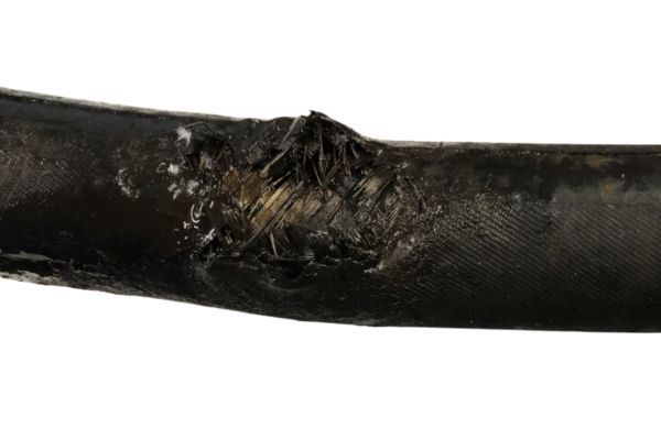
External Abrasion
One of the most prevalent causes of hydraulic hose failure is external abrasion. This occurs when the hose’s outer cover is worn down through continuous contact with surrounding equipment, other hoses, or environmental factors like debris and rough surfaces. This wear and tear can lead to the degradation of the hose’s outer layer, exposing the reinforcement layers beneath. Once the reinforcement is compromised, the hose’s ability to withstand pressure is significantly reduced, leading to leaks or catastrophic failures.
Common Sources
The common sources of abrasion include but are not limited to:
Equipment Contact: Hoses rubbing against parts of the machinery they are attached to or other nearby structures.
Debris and Particulate Matter: Exposure to small, hard particles that can erode the hose’s outer layer over time.
Environmental Conditions: Operations in harsh environments, where hoses are exposed to rough terrain, sharp edges, or corrosive elements.

Prevention Tips
To combat the issue of abrasion and wear, several strategies can be employed:
Proper Hose Routing: Ensuring hoses are correctly routed to avoid unnecessary contact with abrasive surfaces or high-risk areas.
Protective Sleeves: Utilizing protective sleeves or covers made from materials designed to withstand abrasion can shield hoses from external damage.
Regular Inspections: Conducting regular inspections of hydraulic hoses as part of a maintenance routine can help identify early signs of wear and tear, allowing for proactive measures before failure occurs.
Improper Installation
Installation Errors
Improper installation of hydraulic hoses is a significant contributor to their premature failure. Errors during installation can range from using hoses of inappropriate length, failing to adhere to the required bending radius, or incorrect attachment of fittings. Each of these errors can introduce undue stress on the hose, leading to weak points where failure is more likely to occur. For instance, a hose that is too short may not have sufficient slack to accommodate movement or vibration, whereas a hose that is too long could lead to kinking or unnecessary abrasion against surrounding components.
Consequences
The consequences of improper installation are multifaceted and can severely impact the integrity and performance of hydraulic systems. Increased stress on the hose from stretching, compression, or bending beyond its design limits can lead to the development of leaks, the appearance of cracks, or even a complete rupture. These failures not only necessitate costly repairs or replacements but also pose significant safety risks to operators.
Installation Best Practices
To ensure the longevity and reliability of hydraulic hoses, adhering to the following best practices during installation is crucial:
Adherence to Manufacturer Specifications: Always consult and follow the manufacturer’s guidelines for hose length, bending radius, and fitting types. Manufacturers provide these specifications to optimize the performance and durability of their products under operational conditions.
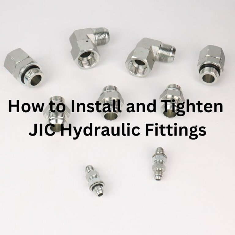
Correct Fitting Attachment: Make sure that fittings are securely and correctly attached to the hose. This includes using the right tools to crimp or secure the fittings without damaging the hose structure.
Consideration of Movement and Vibration: Account for potential movement and vibration in the system’s design to prevent undue stress on the hoses. This may involve incorporating slack in the hose length or using clamps to secure hoses away from points of high wear or potential abrasion.
Professional Training: Ensure that personnel involved in the installation of hydraulic hoses are adequately trained and familiar with best practices and safety guidelines. Proper training can significantly reduce the risk of installation errors and subsequent hose failures.
Temperature Extremes
Temperature Effects
Hydraulic hoses are designed to operate within a specific temperature range, and deviating from these recommended limits can significantly impact their performance and longevity. Operating hoses at temperatures higher than recommended can lead to the degradation of the hose material, resulting in softening, loss of strength, and an increased risk of rupture. Conversely, exposure to temperatures below the minimum can cause hoses to become brittle, less flexible, and more susceptible to cracking or breaking. Both scenarios undermine the structural integrity of the hose and its ability to maintain a secure conveyance of hydraulic fluid under pressure.
Examples
High-Temperature Failure: In an industrial setting, a hydraulic hose used near a high-heat source exceeded its maximum temperature rating, leading to the softening of its rubber components. This resulted in a leak that not only caused a significant operational delay but also posed safety risks due to the sudden loss of hydraulic control.
Low-Temperature Breakdown: In a cold climate, construction equipment experienced hydraulic hose failure because the hoses became too rigid in sub-zero temperatures. This rigidity led to cracks forming in the hose when it was subject to movement, ultimately causing a complete system failure.
Guidelines
To mitigate the risks associated with temperature extremes, consider the following guidelines:
Suitable Temperature Ratings: Select hoses that have temperature ratings appropriate for the operating environment of the machinery. Manufacturers specify these ratings to ensure optimal performance and durability.
Use of Insulation or Cooling Systems: In applications where hoses are exposed to high temperatures, consider using insulation to protect them from heat sources. Similarly, in hot operating environments, cooling systems can help maintain hydraulic fluid at a safe operating temperature.
Regular Monitoring: Implement a routine check to monitor the condition of hoses operating in extreme temperatures. This can help identify potential issues before they lead to failure.
Environmental Considerations: When selecting hydraulic hoses, consider the environmental conditions they will be exposed to, including the potential for temperature fluctuations between day and night or seasonal changes.
Chemical Compatibility
Compatibility Issues
Selecting hydraulic hoses that are compatible with both the hydraulic fluid they will carry and potential external contaminants is crucial for ensuring the longevity and reliability of the hose. Hydraulic fluids vary in chemical composition, and not all hose materials are resistant to the specific types of fluids or external chemical exposures they may encounter. Incompatibility between the hose material and the fluid can lead to hose degradation, compromising the system’s integrity and safety.
Material Degradation
Chemical exposure can cause various forms of degradation in hose materials, such as:
Swelling and Softening: Certain rubber materials may absorb fluids, leading to swelling and a loss of physical strength. This can result in a hose that is more prone to abrasion and tear.
Cracking and Hardening: Exposure to aggressive chemicals or even prolonged exposure to certain hydraulic fluids can cause the hose material to harden and become brittle, leading to cracks and leaks.
Chemical Reaction: Some hose materials may chemically react with specific hydraulic fluids or external contaminants, causing the material to degrade or the fluid to become contaminated, which can adversely affect system performance.
Material Selection Recommendations
When selecting a hydraulic hose, consider the following to ensure chemical compatibility:
Consult Compatibility Charts: Manufacturers often provide chemical compatibility charts for their hose materials. These charts are an invaluable resource for determining which materials are suitable for use with specific hydraulic fluids and external contaminants.
Understand the Application Environment: Consider all possible chemical exposures in the application environment, not just the hydraulic fluid. This includes environmental contaminants, cleaning agents, and any other chemicals the hose might come into contact with.
Select Specialty Hoses for Harsh Environments: For applications involving aggressive chemicals, high temperatures, or other harsh conditions, specialty hoses designed for chemical resistance may be necessary. These hoses are made from materials specifically engineered to withstand challenging environments.
Pressure Surges and Overloading
Pressure Rating Exceedance
Exposing hydraulic hoses to pressures beyond their rated capacity is a precarious practice that can lead to catastrophic failures. Hydraulic hoses are designed to operate safely up to a specific maximum pressure. When this threshold is exceeded, even momentarily due to pressure surges, the integrity of the hose is compromised. This can result in the weakening of the hose structure, leading to bursts and leaks. A burst hose not only halts operations due to the immediate loss of hydraulic fluid but also poses significant safety risks to nearby personnel, potentially resulting in injuries from the sudden release of high-pressure fluid.
Understanding Impulse Cycles
Impulse cycles refer to the rapid fluctuations in pressure and velocity that hoses experience during regular hydraulic system operations. These cycles can be particularly demanding on hoses, as the repeated pressures and relaxations can stress hoses beyond their limits over time. Selecting hoses that are designed to endure the specific impulse cycles of a system is crucial. Hoses that are not suited for the system’s pressure dynamics may fail prematurely due to fatigue, leading to leaks or bursts. Manufacturers often test hoses for a specific number of impulse cycles at a given pressure to ensure reliability under dynamic conditions.
Preventive Measures
To prevent pressure-related failures in hydraulic systems, consider the following tips:
Employ Pressure-Relief Valves: Incorporating pressure-relief valves in the hydraulic system can help manage unexpected surges in pressure, thereby protecting hoses from being subjected to pressures that exceed their design limits.
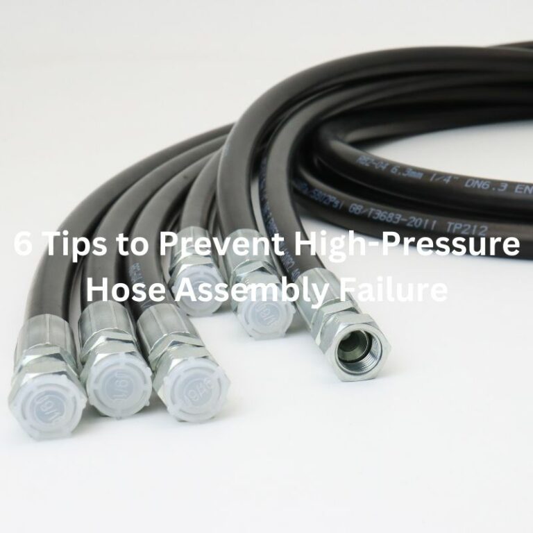
Choose the Right Hose: Select hoses based on the maximum operating pressure of the system, including any potential surges. Ensure that the hose’s rated pressure meets or exceeds the highest pressure it will encounter during operation.
Regular System Checks: Regularly monitor the hydraulic system’s pressure levels to identify any fluctuations that may indicate issues with pressure control components. Early detection of pressure spikes can prevent hose failures.
Use Proper Hose Assemblies: Ensure that hose assemblies, including fittings and connectors, are also rated for the system’s maximum pressure. Mismatched components can create weak points prone to failure under high-pressure conditions.
Age and Deterioration
Lifecycle and Aging
Over time, hydraulic hoses naturally undergo aging, a process that can significantly impact their functionality and integrity. Signs of aging in hoses include visible cracking on the surface, increased stiffness, and a loss of elasticity. These changes are indicators that the hose’s material properties are degrading, which can compromise its ability to withstand operational pressures and may lead to leaks or bursts under normal conditions.
Environmental Factors
Environmental factors play a significant role in accelerating the deterioration of hydraulic hoses. Exposure to UV light, for instance, can cause the materials in the hose to break down, leading to brittleness and cracking. Similarly, ozone, a common atmospheric pollutant, can also cause cracking and degradation of rubber components. These environmental elements can drastically shorten the expected lifespan of a hydraulic hose, leading to premature failure.
Maintenance Strategies
To combat age and environmental deterioration, implementing a proactive maintenance strategy is essential. Here are some tips to help prevent failures due to aging:
Regular Inspections: Conduct periodic visual inspections of all hydraulic hoses, looking for signs of aging, wear, or environmental damage. Pay special attention to hoses exposed to harsh conditions.
Environmental Protection: Where possible, protect hoses from direct sunlight, extreme temperatures, and ozone. This can involve rerouting hoses away from sources of heat or UV exposure, or using protective sleeves.
Scheduled Replacement: Based on the manufacturer’s recommendations and your observations from regular inspections, establish a schedule for replacing hoses that are nearing the end of their useful life. This approach prevents unexpected failures and allows for planned downtime, if necessary.
Contamination
Internal Wear from Contamination
Contamination within the hydraulic fluid is a critical concern that can lead to hose and system failure. Particulate matter, such as dirt, metal shavings, and other debris, can cause significant internal wear and tear on hydraulic hoses and components. This wear can degrade the hose’s interior surfaces, leading to leaks, blockages, and ultimately, system failure. Similarly, water contamination in the hydraulic fluid can lead to corrosion of metal components, including fittings and connectors, further compromising the system’s integrity.
Role of Filtration
Effective filtration plays a pivotal role in maintaining a clean hydraulic system. Filtration systems are designed to remove particulate and water contamination from hydraulic fluid, thereby protecting hoses and other hydraulic components from premature wear and failure. Regular maintenance of the filtration system, including timely replacement of filter elements, is essential to ensure that it continues to function effectively, providing clean, contaminant-free fluid for the hydraulic system.
Contamination Prevention Tips
To prevent contamination and maintain system cleanliness, consider the following strategies:
Closed System Handling: Always handle hydraulic fluid in a way that minimizes its exposure to the environment. Use clean containers and funnels when transferring fluid, and ensure that storage containers are sealed properly.
Cleanliness During Hose Replacement: When replacing hydraulic hoses, take care to prevent contaminants from entering the system. Clean the area around connection points thoroughly before disconnecting hoses, and cap or cover open fittings and hoses promptly.
Regular Fluid Analysis: Periodic analysis of hydraulic fluid can provide early warning of contamination issues. This allows for corrective actions, such as filtering or replacing the fluid, before significant damage occurs.
Proper Ventilation: Ensure that the hydraulic system’s reservoir is properly ventilated to prevent the ingress of contaminants while allowing for the release of moisture and pressure.
Conclusion
In this article, we have explored the major causes of hydraulic hose failure, including abrasion, improper installation, temperature extremes, chemical incompatibility, pressure surges, aging and deterioration, and contamination. Understanding these common causes of failure and taking preventative measures is critical to maintaining the integrity and safety of your hydraulic system. We encourage readers to take proactive maintenance measures to minimize these risks. Regular inspections, proper installation, choosing the right materials, and keeping the system clean are key strategies for preventing hose failures. Let’s work together to ensure the reliability and safety of our hydraulic systems.


