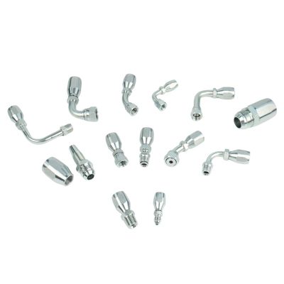
Hydraulic Hose Ferrule Types Everything You Need to Know

Hydraulic Hose Ferrule Types: Everything You Need to Know

Hydraulic Hose Ferrule Types: Everything You Need to Know

What Are Hose Ferrules?

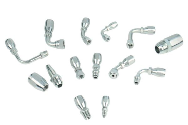
Hose ferrules are critical components in hydraulic systems, serving as connectors between hoses and fittings. These small yet essential components ensure the integrity of the system by providing secure, leak-proof connections that withstand high pressure, vibrations, and extreme environmental conditions. Ferrules clamp onto hoses, maintaining pressure and preventing leaks or disconnects. The right ferrule helps maintain pressure, ensures the longevity of the hose, and prevents potential system failures that could lead to costly downtime or accidents.

Overview of Hose Ferrules

Basic Structure and Function

Ferrules are small but vital components in hydraulic systems, typically made from metal. These cylindrical rings are designed to crimp around the end of a hydraulic hose, tightly securing the hose to its fitting. Their primary function is to reinforce the connection between the hose and fitting, preventing the hose from loosening or detaching under the intense pressure that hydraulic systems often generate.

When a ferrule is placed over the hose, a crimping tool is used to apply uniform pressure to the ferrule, compressing it firmly around the hose. This compression creates a permanent, robust connection that maintains the integrity of the system even in demanding conditions. Without ferrules, hoses would be susceptible to leaks and disconnection, leading to system inefficiencies or failures.

The Role of Ferrules in Hydraulic Hose Assemblies

Ferrules serve as the key component in forming a leak-proof seal between the hydraulic hose and its fitting. By securely gripping the hose, the ferrule prevents the escape of hydraulic fluid and ensures that the system can operate under high pressure without risk of leakage or hose dislodgement.

This secure connection is critical for maintaining the efficiency of hydraulic systems, which rely on consistent fluid pressure to perform their functions. Whether in industrial machinery, construction equipment, or automotive applications, a well-installed ferrule is indispensable for the safe and reliable operation of the entire system.

Significance of Proper Ferrule Selection

The importance of selecting the correct ferrule for a hydraulic hose assembly cannot be overstated. A ferrule that is incompatible with the hose or fitting can lead to various issues, from minor fluid leaks to catastrophic system failures. Such failures can result in significant downtime, costly repairs, and even safety hazards.

Types of Hose Ferrules

Hose ferrules are categorized based on their application, pressure rating, and compatibility with different hoses. The correct ferrule selection depends on the hydraulic system’s requirements, such as the type of hose used, the pressure it must withstand, and the operating environment.

00400 Ferrule

Application: High-pressure hydraulic systems

Suitable Hoses: Spiral hydraulic hoses like SAE 100R12, 4SP, 4SH

Description: These ferrules are designed for heavy-duty industrial applications where extreme pressure and durability are required. They provide secure connections for high-pressure hoses used in demanding environments such as construction and mining.

00400 Hydraulic Hose Ferrules Topa

00018 Ferrule

Application: Low-pressure systems, such as pneumatic systems or low-stress hydraulic systems

Suitable Hoses: SAE 100R7, R8

Description: Ideal for small-scale systems where high pressure is not required, these ferrules provide sufficient protection for pneumatic and low-pressure hydraulic hoses in light-duty applications.

00110 Ferrule

Application: Medium-pressure systems

Suitable Hoses: Braided hoses like SAE 100R1AT/1SN, 1SC

Description: Used in medium-pressure hydraulic systems, these ferrules are commonly found in applications where the hose must withstand moderate pressure without failure, such as in agricultural and light industrial machinery.

00200 Ferrule

00200 hydraulic ferrule Topa

Application: High-flow, high-pressure systems

Suitable Hoses: Spiral and braided hoses like SAE 100R2AT、 2SN, 2SC

Description: Built for heavy machinery requiring strong, durable connections, these ferrules can handle high flow rates and pressures, making them essential for hydraulic systems in industries like construction and material handling.

00TF0 Ferrule

Application: Specialized, corrosion-resistant applications

Suitable Hoses: PTFE and other chemical-resistant hoses

Description: These ferrules are used in environments where corrosion resistance is crucial, such as chemical plants or food processing industries. They are designed to handle PTFE and other hoses exposed to aggressive chemicals.

00621 Ferrule

Application: Extreme environments with high pressure and chemical exposure

Suitable Hoses: Synthetic rubber hoses with stainless steel braids; R13, R15

Description: Ideal for extreme environments, these ferrules provide extra protection against high temperatures and corrosive chemicals, ensuring that the hose and fitting maintain their integrity under harsh conditions.

03310 Ferrule

Application: Heavy machinery with high vibrations and pressure

Suitable Hoses: SAE R1 R2

Description: These ferrules are designed to absorb high vibrations and pressure, making them well-suited for heavy machinery. Their robust construction helps prevent wear and tear in high-vibration environments.

00518 Ferrule

00518 Hose Ferrule Topa

Application: Versatile high-pressure applications

Suitable Hoses: SAE 100R5; Reusable hydraulic fitting ferrule

Description: This ferrule type is versatile and can handle various high-pressure industrial applications, providing reliable performance across different industries, from manufacturing to transportation.

00210 Ferrule

Application: Medium-pressure systems

Suitable Hoses: SAE 100R2AT 2SN/2SC

Description: These ferrules are compatible with medium-pressure hoses and are often used in hydraulic systems that require dependable, mid-range pressure performance, such as automotive and industrial machinery.

00401 Ferrule

Application: General-purpose hydraulic applications

Suitable Hoses: Multipurpose hoses like 4SP

Description: Designed for general-purpose use, these ferrules are suitable for a wide range of hydraulic applications where versatility and reliability are key. They provide secure connections for multipurpose hoses used in various industrial settings.

Material Types

Steel Ferrules:

Known for their strength and durability, steel ferrules are the go-to choice for high-pressure applications. They can handle extreme pressures and are often used in industries that require robust and reliable connections, such as heavy machinery and industrial equipment.

Stainless Steel Ferrules:

Offering superior corrosion resistance, stainless steel ferrules are essential for harsh environments where exposure to chemicals or saltwater is common. They are frequently used in marine applications, chemical plants, and industries where hygiene and corrosion resistance are critical.

Brass Ferrules:

Brass ferrules are typically used in low-pressure, non-corrosive environments. They offer a good balance of strength and corrosion resistance, making them suitable for light-duty hydraulic systems, pneumatic applications, and areas where chemical exposure is minimal.

Composite Ferrules:

Composite ferrules are lightweight and used in specialized applications where adaptability and material-specific advantages are needed. They are often employed in industries that require non-metallic solutions, such as food processing, pharmaceutical production, and sensitive electronic environments.

Key Factors to Consider When Choosing Ferrules

Compatibility with Hose Material

Ensuring that the ferrule material is compatible with the hose material is essential for creating a long-lasting, reliable connection. Mismatched materials can lead to rapid wear, corrosion, and eventual system failure. For example, stainless steel ferrules should be paired with hoses that are resistant to chemical exposure and corrosion to maintain their structural integrity. This is particularly crucial in systems where the hose material needs to withstand aggressive chemicals, high temperatures, or abrasive conditions. Engineers must consider both the mechanical properties and the chemical compatibility of the ferrule and hose materials when making their selection.

Pressure and Temperature Ratings

The operational pressure and temperature of the hydraulic system significantly influence the choice of ferrule. Each ferrule type has specific pressure and temperature limits, and exceeding these limits can result in failure. For instance, using a ferrule rated for medium pressure in a high-pressure system can cause leaks, hose blowouts, or even catastrophic system failures. Similarly, operating outside of the temperature range for which the ferrule is rated can lead to material fatigue, cracking, or loss of connection strength. When selecting a ferrule, always reference the manufacturer’s pressure and temperature ratings to ensure they match the hydraulic system’s operational conditions.

Corrosion Resistance and Environmental Factors

Corrosion resistance is another critical factor to consider, especially in environments where the ferrule will be exposed to corrosive substances such as chemicals, saltwater, or humidity. Stainless steel ferrules offer superior corrosion resistance, making them ideal for use in marine, chemical, and food processing environments. However, for low-pressure or non-corrosive environments, brass or steel ferrules may be sufficient. It is crucial to assess the environmental conditions the ferrule will face and choose a material that can withstand those specific challenges without degrading over time.

Size and Application

The size of the ferrule must be precisely matched to the hose to ensure a secure fit. Improper sizing can result in leaks, insufficient crimping, or even hose detachment. Engineers need to carefully measure the internal and external diameters of the hose and ensure that the ferrule dimensions are appropriate for the application. Additionally, the specific application of the hydraulic system—whether it’s in heavy machinery, chemical processing, or light-duty equipment—will dictate the type of ferrule required. The ferrule’s design and material should align with the operational demands of the system, including factors such as vibration, flow rate, and pressure stability.

Installation and Best Practices

Crimping Techniques

Installing ferrules properly is critical to ensuring the long-term performance of hydraulic hose assemblies. The crimping process is one of the most important steps in the installation of ferrules. Specialized crimping tools and machines apply uniform pressure to the ferrule, compressing it evenly around the hose and creating a leak-proof seal. It is essential to follow precise crimping techniques, as uneven compression can compromise the integrity of the seal, leading to leaks or hose slippage. The goal is to apply just the right amount of pressure to secure the ferrule without over-compressing the hose material.

When crimping, it’s important to ensure that the ferrule is aligned correctly with both the hose and fitting before applying pressure. Any misalignment can result in uneven crimping, which may weaken the connection and lead to premature failure.

Importance of Using the Right Tools and Machines

Crimp Hydraulic Hoses

The tools and machines used for crimping must be appropriate for the specific ferrule type and hose size. Using incorrect tools can result in uneven or inadequate compression, potentially causing leaks, slippage, or even catastrophic failure of the hose assembly. Manufacturers provide specific crimping guidelines, including recommended tools, machine settings, and techniques, which should always be followed to ensure a reliable installation.

For instance, hand crimpers might be suitable for smaller or low-pressure applications, while hydraulic crimping machines are often required for high-pressure systems or larger hose sizes. Investing in the right crimping equipment not only improves installation quality but also ensures consistency across multiple assemblies.

Common Installation Mistakes

Several common installation mistakes can significantly reduce the lifespan of hose ferrules and lead to system failures. These include:

Misalignment: If the ferrule is not aligned properly with the hose and fitting, the crimping process will not distribute pressure evenly, leading to weak spots in the connection that can leak or fail.

Over-Crimping: Applying too much pressure during crimping can damage the hose or ferrule, leading to cracks, deformations, or constrictions that impede fluid flow.

Under-Crimping: Insufficient pressure can result in a loose connection, allowing the hose to slip out of the ferrule over time or leak under pressure.

Avoiding these mistakes requires careful adherence to the manufacturer’s crimping instructions and ensuring that the ferrule is correctly positioned before crimping begins. Proper training for technicians is also essential to minimize these risks.

Regular Maintenance and Inspection

Once the ferrules are installed, regular maintenance and inspection are critical to ensure their long-term performance. Over time, ferrules may experience wear due to environmental factors, vibration, or general system use. Routine inspections can detect early signs of wear and tear, such as cracking, corrosion, or loosening.

Regular maintenance includes checking the tightness of connections, cleaning the ferrules to remove debris or contaminants, and replacing any worn components before they fail. By performing these preventive maintenance tasks, you can extend the life of your hydraulic hose assemblies and prevent unexpected downtime or system failures.

Conclusion

This article has covered the different types of hose ferrules, the importance of proper selection, and best practices for installation and maintenance. Understanding these factors is essential for ensuring system reliability and safety. When selecting a hose ferrule, always consider the application, pressure, material, and environmental conditions. Proper installation and regular maintenance are critical for avoiding system failures.

FAQ

A hose ferrule is a small metal ring that is crimped around the end of a hydraulic hose to secure it to a fitting, creating a tight, leak-proof connection in hydraulic systems.

Choosing the right ferrule is crucial for maintaining system integrity, preventing leaks, and ensuring the hydraulic system operates safely under pressure.

Ferrule selection depends on the hose type, pressure rating, material compatibility, and the environment the system operates in. Always match the ferrule specifications to the hose and application.

Common materials include steel, stainless steel, brass, and composite materials. Each material is chosen based on the specific application and environmental conditions.

Avoid misalignment, over-crimping, and under-crimping, as these mistakes can lead to leaks, hose slippage, or system failure.

Ferrules should be inspected regularly as part of routine maintenance, especially in high-pressure or corrosive environments, to identify signs of wear, corrosion, or loosening before failure occurs.

Contact Topa

Have a question or suggestion? Fill out the form below to get in touch with one of our experts.

How to Replace Broken Hose Ferrules

How to Replace Broken Hose Ferrules

How to Replace Broken Hose Ferrules

Table of Contents

Introduction

Without properly functioning ferrules, the hydraulic system would be vulnerable to leaks, pressure drops, and potential failure, which could lead to significant operational disruptions. Damaged ferrules can lead to leaks that not only reduce system efficiency but also pose serious risks, including fluid spills, equipment malfunction, and operator injury. By addressing broken ferrules early, you can prevent more significant issues, extend the lifespan of your equipment, and ensure smooth, uninterrupted operations.

Identifying Broken Hose Ferrules

Visual Signs of Ferrule Damage

Regular visual inspection of hose ferrules is crucial to identifying potential issues early. Look for the following key signs of damage:

Cracking: Cracks on the surface of the ferrule are a clear indicator of damage. These fractures can occur due to over-crimping, material fatigue, or stress caused by constant high pressure. Cracked ferrules no longer provide a reliable seal, leading to fluid leaks or pressure loss.

Corrosion: Ferrules made from metal, especially those exposed to moisture or harsh chemicals, are susceptible to corrosion. Rust weakens the ferrule’s structure, reducing its effectiveness in maintaining a proper seal between the hose and fitting.

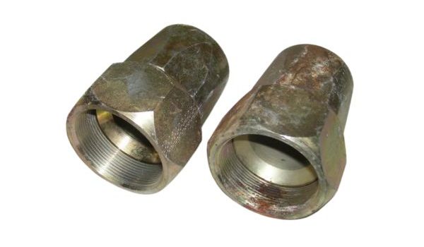
Deformation: Bending or warping of the ferrule suggests that it has been subjected to excessive force, improper crimping, or the use of incorrect tools during installation. Deformed ferrules can no longer perform their intended function properly, leading to system inefficiencies or potential failure.

Leaking Hydraulic Fluid or Reduced System Performance

Hose Ferrule rust

A broken or compromised ferrule will often lead to fluid leaks around the connection point. Leaks can range from slow, steady drips to more significant fluid loss. Reduced hydraulic performance is another clear indicator of ferrule failure. This can manifest as:

Inconsistent Pressure: A system with a failing ferrule may experience inconsistent or erratic pressure levels, impacting the overall performance and responsiveness of the machinery.

Decreased Fluid Flow: When ferrules are compromised, they may partially obstruct the hose or cause a poor seal, reducing the fluid flow rate through the system.

Functional Indicators of a Failing Ferrule

In addition to visual signs, functional indicators can help detect a failing ferrule. These signs typically present as abnormal behavior within the hydraulic system:

Changes in Hydraulic Pressure: If the ferrule is damaged, the hydraulic system may struggle to maintain steady pressure. Pressure fluctuations, especially when under load, may indicate that the ferrule is failing to maintain a tight seal.

Unusual Noise or Vibration in the System: A broken ferrule can cause irregularities in fluid movement, leading to vibrations or unusual noises such as hissing or squealing sounds. These noises are often a result of air entering the system through the compromised connection or pressure loss.

Safety Precautions When Inspecting Ferrules

Before conducting any inspection of hose ferrules, it’s critical to follow proper safety protocols. Hydraulic systems operate under high pressure, and mishandling them can be dangerous. Always adhere to the following safety precautions:

Wear Protective Gear: Personal protective equipment (PPE) such as gloves, safety glasses, and protective clothing should be worn to prevent injury from hydraulic fluid exposure, high-pressure leaks, or contact with sharp edges on damaged ferrules.

Depressurize the System: Ensure that the hydraulic system is fully depressurized before beginning any inspection or repair. Residual pressure within the system can cause sudden fluid release, which may result in serious injury.

Handle Fluids Cautiously: Hydraulic fluid can be hazardous if mishandled. Be sure to contain any leaks or spills promptly, and avoid contact with skin or eyes. If necessary, dispose of hydraulic fluid according to local environmental regulations.

Tools and Materials Required for Replacing Hose Ferrules

Essential Tools for Ferrule Replacement

To replace a ferrule, you’ll need the following tools:

Hose Crimping Machine: Necessary for securing the ferrule to the hose. Manual or hydraulic options are available based on your system requirements.

Cutting Tools: A rotary cutter or hacksaw will help in removing the damaged ferrule.

Vice Grips: These help in stabilizing the hose during the replacement process.

Calipers or Measuring Tools: Ensure the correct sizing of new ferrules.

Materials Needed

When replacing a ferrule, it’s essential to have the right materials on hand:

New Hose Ferrules: Make sure they are compatible with your specific hose and application.

Replacement Hose (if necessary): If the hose is damaged, it should also be replaced.

Hydraulic Fluid: You’ll need fluid to refill the system after replacement.

Understanding the Compatibility of Ferrules

It is crucial to match the ferrule with the hose in both size and material:

Choosing the Right Size: Ensure the new ferrule fits the diameter and type of hose you are working with.

Material Considerations: Stainless steel, brass, or aluminum ferrules may be required depending on the hose material (e.g., rubber or PTFE) and the operating conditions.

Considerations for Different Hose Types

Different hoses, such as rubber or PTFE, require unique ferrule types and installation methods. Always consult the hose manufacturer’s specifications to ensure compatibility.

Step-by-Step Guide to Replacing Broken Hose Ferrules

Step 1: Preparing for Replacement

Before beginning the replacement process, it’s essential to prepare both the work area and the system to ensure safety and efficiency. Follow these steps:

Safely Disconnect the Hose

Begin by isolating the hose from the hydraulic system. This involves disconnecting the hose from the machinery or system it is attached to. Make sure the machinery is turned off to prevent any unexpected activation during the replacement process.

Depressurize the Line: Hydraulic systems operate under high pressure, so it’s critical to fully depressurize the line before beginning any work. Use the system’s designated valve or mechanism to release pressure safely. Failure to do so can result in accidents or injury when the ferrule is removed.

Drain Hydraulic Fluid (if necessary)

If the hose in question is carrying hydraulic fluid, carefully drain the fluid to prevent spillage. This step is necessary when the hose is still attached to parts of the system where residual fluid might remain.

Contain Spills: Use appropriate containers to catch and contain any fluid that may escape during the process. Be prepared to clean up any accidental spills immediately.

Ensure No Pressure in the System

Double-check that the system is entirely depressurized and that there are no trapped air pockets or residual pressure. Even minimal pressure can cause fluid to escape forcefully when the hose or ferrule is disconnected.

Safety First: Always prioritize safety. Wear protective gear such as gloves, goggles, and coveralls to shield yourself from hydraulic fluid or debris during the process.

Hydraulic Hose Assembly cut hose

Step 2: Cutting Off the Damaged Ferrules

Once the system is safely disconnected and depressurized, the next step is to remove the damaged ferrule.

Proper Cutting Techniques

Using a rotary cutter, hacksaw, or another appropriate tool, carefully cut the ferrule away from the hose. The key here is precision: you want to remove the ferrule without damaging the hose underneath.

Make a Clean Cut: The cut should be smooth and even, without jagged edges. A clean cut will help ensure that the hose remains in good condition for the installation of the new ferrule.

Specialized Tools

Ferrule removal tools are specifically designed to help you cut through the metal of the ferrule without nicking or slicing into the hose itself. If possible, opt for these specialized tools, as they provide greater control and safety during the removal process.

Protect the Hose Surface: Take your time when cutting to ensure that the hose is not damaged in the process. A damaged hose will need to be replaced entirely, which could complicate the repair.

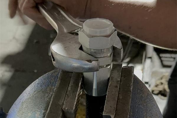
Use a Vice or Clamp: Stabilizing the hose in a vice or clamp can help keep it steady while you cut the ferrule, reducing the risk of slippage and accidental damage.

Step 3: Preparing the Hose End

Once the damaged ferrule has been successfully removed, the next step is to prepare the hose for the installation of the new ferrule.

Clean the Hose End

Before installing the new ferrule, make sure the hose end is clean and free of debris, oil, or any remaining hydraulic fluid. Use a clean cloth or rag to wipe down the area thoroughly.

Check for Debris: Even small particles of debris can interfere with the crimping process and the secure attachment of the new ferrule, so it’s essential to ensure the hose is spotless.

Inspect for Additional Damage

Take a close look at the hose after the ferrule is removed. Check for any signs of additional damage, such as cracks, abrasions, or excessive wear. These could compromise the integrity of the hose and the newly installed ferrule.

Replace the Hose if Necessary: If the hose shows signs of significant wear or damage, replacing it entirely may be a better option than trying to salvage it with a new ferrule. A damaged hose could lead to further complications down the line.

Cut the Hose End if Required: If the hose end appears frayed or damaged, cut back the hose to a point where it is intact and undamaged. This will provide a solid base for installing the new ferrule.

Step 4: Installing the New Ferrule

Now that the hose is properly prepared, it’s time to install the new ferrule.

Align the Hose and Ferrule

Position the new ferrule over the prepared end of the hose. Ensure that the hose end is straight and properly aligned with the ferrule.

Check for Fit: The ferrule should fit snugly over the hose end without too much force. If it feels too tight or too loose, you may need to double-check that you’re using the correct size ferrule for your hose.

Crimp the Ferrule

Using a hose crimping machine, secure the ferrule to the hose. The crimping machine applies uniform pressure to the ferrule, squeezing it tightly onto the hose to create a leak-proof seal.

Step-by-Step Crimping: Adjust the crimping machine to the correct setting based on the ferrule size and material. Follow the manufacturer’s instructions to ensure a precise crimp. Generally, you’ll need to feed the hose and ferrule into the crimping machine and activate the machine to apply the crimping force.

Manual Methods: If using a manual crimping tool, apply consistent pressure to achieve a secure fit. It’s crucial to ensure even pressure across the ferrule to avoid over-crimping one side and under-crimping the other.

Check Crimping Machine Calibration: Ensure that the crimping machine is calibrated correctly. Incorrect settings can result in either over-crimping, which could damage the hose, or under-crimping, which could lead to a weak connection.

Visual Inspection: After crimping, visually inspect the ferrule to ensure it’s evenly crimped and securely attached to the hose.

crimping hose Ferrule

Step 5: Testing the Connection

Once the new ferrule is installed, the final step is to test the connection to ensure it’s secure and leak-free.

Reconnect the Hose

Carefully reattach the hose to the hydraulic system, ensuring all fittings are securely fastened. Double-check all connections for proper alignment and tightness.

Follow System Guidelines: Reconnection should be done following the hydraulic system’s specific guidelines to ensure compatibility and safety.

Test for Leaks

After reconnecting the hose, pressurize the hydraulic system slowly and check for leaks around the newly installed ferrule. Look for any signs of fluid escaping or reduced pressure within the system.

Visual Inspection: Look for visible signs of leaks or drips at the connection points. If leaks are found, depressurize the system and double-check the ferrule installation.

Listen for Noise: Pay attention to any hissing or unusual noises that may indicate a leak or poor fit.

Pressure Testing

Use a pressure tester to confirm that the system is holding the correct pressure. This final test ensures that the newly installed ferrule is functioning properly and that the hydraulic system is operating as expected.

Monitor Pressure Levels: Watch the pressure gauge during the test to ensure that the system maintains stable pressure without fluctuation or loss.

Final Adjustments: If any issues arise during testing, such as minor leaks, re-crimp the ferrule or re-secure the fittings as necessary. Make sure the system is performing optimally before considering the job complete.

Troubleshooting Common Issues During Replacement

Ferrule Won’t Crimp Properly

Sometimes, ferrules may not crimp as expected, leading to a poor fit or insecure connection. Here’s how to address this issue:

Check Tool Settings: One of the most common causes of improper crimping is incorrect tool settings. Double-check that your crimping machine is calibrated to the correct settings based on the size and material of the ferrule you are working with. Machines with adjustable settings may have options for different ferrule sizes, and it’s crucial to select the right one to avoid over- or under-crimping.

Inspect Ferrule Size: Another possible issue is that the ferrule size doesn’t match the hose size. A ferrule that is too large or too small will not crimp properly. Ensure you are using the correct ferrule for the hose diameter and material. Measure both the hose and ferrule with calipers if necessary to confirm they are compatible.

Inspect Crimping Jaws: Ensure the crimping jaws of the machine are clean and in good condition. Debris or worn-out jaws may prevent proper crimping. If necessary, clean or replace the jaws before attempting to crimp again.

If these checks don’t resolve the issue, consider switching to a different crimping tool or consulting the manufacturer’s specifications to ensure compatibility.

Hose Damage During Ferrule Removal

When removing a damaged ferrule, there’s a risk of cutting too deep into the hose, leading to unnecessary damage. To avoid this issue, consider the following:

Using Proper Tools: Specialized ferrule removal tools are designed to minimize the risk of hose damage. These tools allow you to cut through the ferrule while avoiding contact with the hose surface. Rotary cutters or ferrule splitters are often the best choices for precision removal. Avoid using crude tools like regular pliers or saws, which may increase the risk of cutting too deep.

Take Extra Care: It’s essential to work slowly and carefully when removing the ferrule. Make gradual, controlled cuts to ensure you don’t accidentally slice into the hose material. If possible, stabilize the hose with a vice or clamp, which allows you to focus on cutting the ferrule without the risk of the hose moving or slipping.

Inspect the Hose Regularly: As you cut away the ferrule, stop periodically to inspect the hose and ensure that you haven’t nicked or damaged it. If you do accidentally cut into the hose, assess the extent of the damage. In cases of minor superficial damage, you may still be able to proceed, but more severe damage will likely require hose replacement.

Leaks After Replacement

Leaks after installing the new ferrule are a common issue and typically result from improper crimping or alignment. Here’s how to address leaks:

Recheck Installation: Start by thoroughly inspecting the ferrule to ensure it has been correctly aligned and securely crimped onto the hose. A misaligned ferrule will fail to create a tight seal, leading to leaks. Make sure that both the hose and ferrule are properly prepared and that no debris or misalignment is preventing a good connection.

Re-crimp if Necessary: If the crimp is not tight enough, you may need to re-crimp the ferrule. Ensure that you are applying the correct pressure according to the manufacturer’s guidelines. Under-crimping can cause a loose connection, while over-crimping may damage the ferrule or hose. Carefully recalibrate the crimping machine and try again, making sure to apply even pressure throughout the process.

Check for Other Issues: If leaks persist after re-crimping, inspect other potential sources of the problem, such as damaged hose material, worn-out fittings, or cracks in the hydraulic components. In some cases, the issue may not be with the ferrule at all but with the surrounding parts of the hydraulic system.

Perform a Pressure Test: Once the leak is addressed, perform a final pressure test to confirm that the hydraulic system is functioning correctly and that there are no further leaks. Monitor the system for a few minutes to ensure stable pressure and fluid flow.

Conclusion

Replacing broken hose ferrules promptly and correctly is essential for maintaining the safety and efficiency of hydraulic systems. By identifying damaged ferrules through visual inspections and functional indicators, and by using the right tools and following the correct procedures, you can ensure a successful replacement. The process, from disconnecting the hose and removing the damaged ferrule to crimping the new one and testing for leaks, requires careful attention at every step. Always prioritize safety, conduct regular maintenance checks, and seek professional help if necessary to avoid compromising system performance.

FAQ

A hose ferrule is a metal sleeve crimped onto the end of a hose to securely connect it to a fitting, preventing leaks in hydraulic systems.

Hose ferrules can fail due to wear and tear, improper installation, exposure to harsh environments, or material fatigue.

Visual signs such as cracking, corrosion, and deformation, along with hydraulic fluid leaks or reduced system performance, indicate the need for replacement.

Yes, with the right tools and knowledge, you can replace a hose ferrule yourself, but ensure safety procedures are followed carefully.

You’ll need a hose crimping machine, cutting tools, ferrule removal tools, and possibly a pressure tester to ensure a successful replacement.

Regular maintenance checks, proper installation techniques, and using the correct ferrules for your hose type can help prevent future failures.

Contact Topa

Have a question or suggestion? Fill out the form below to get in touch with one of our experts.

Heavy-Duty vs Light-Duty Metric Fittings Which is Right for You

How to Ensure Leak-Free Hydraulic Systems

How to Ensure Leak-Free Hydraulic Systems

Table of Contents

Introduction

Hydraulic fluid leakage can pose serious safety risks, such as slippery surfaces and potential exposure to harmful substances. The environmental impact is also considerable, as leaking hydraulic fluid can contaminate soil and water sources, leading to regulatory fines and cleanup costs. The primary goal of this article is to offer practical steps and expert guidance on ensuring a leak-free hydraulic system. By addressing common causes of leaks and outlining preventive measures, we aim to help you maintain the reliability and efficiency of your systems while minimizing downtime and protecting both the environment and workplace safety.

Common Causes of Hydraulic Leaks

Overview of Leak Sources

Hydraulic leaks are a frequent issue in industrial operations, typically arising from various sources. The most common causes of hydraulic leaks are wear and tear on components, improper installation procedures, and mismatched components. Over time, seals and O-rings can degrade due to exposure to harsh conditions, and fittings or hoses may be incorrectly selected or installed, leading to incompatibility or stress within the system. By understanding the origins of these leaks, operators can implement more effective preventive measures.

Worn Seals and O-rings

Cause: Seals and O-rings are vital components in maintaining the integrity of systems. However, as they age, they become vulnerable to degradation. Continuous exposure to hydraulic fluids, fluctuating temperatures, and chemical substances causes the materials to harden, crack, or lose flexibility. Extreme heat can accelerate this process, while chemical reactions with the hydraulic fluid can cause swelling or erosion, compromising the seal.

Prevention: The key to preventing leaks from worn seals and O-rings is regular inspection and timely replacement. Using high-quality materials specifically designed to withstand the hydraulic fluid, temperature range, and pressure of your system is essential. Ensuring that replacement seals are compatible with both the system and the media is crucial for long-term performance. Proactive maintenance schedules should include the periodic replacement of these critical components before they fail.

Leaks in Hydraulic Ports

Incorrect Fitting Selection

Cause: The incorrect selection of fittings is a common cause of hydraulic leaks. Mismatched fittings—whether in size, material, or type—can lead to poor connections, inadequate sealing, or stress on the components. For example, selecting fittings that cannot handle the pressure or temperature of the system can result in leaks, particularly under high load or extreme conditions.

Prevention: Ensuring leak-free operation requires selecting fittings that match the system’s specific requirements. This includes taking into account factors such as pressure ratings, temperature tolerance, and media compatibility. Using fittings made from appropriate materials and designed for the specific type of hydraulic system (e.g., JIC, ORB, NPT) can reduce the likelihood of leaks. Consulting with suppliers or experts to confirm that fittings are correctly matched to your system’s needs is also recommended.

Misaligned or Damaged Hoses

Cause: Misaligned or damaged hoses are another major source of hydraulic leaks. When hoses are improperly routed or secured, they may experience excessive stress, twisting, or rubbing against surfaces, which can lead to premature wear and damage. Over time, this damage compromises the hose’s integrity, resulting in leaks. Additionally, hoses that are exposed to sharp bends or poor alignment can suffer from internal stress, further increasing the risk of failure.

Prevention: To prevent leaks caused by misaligned or damaged hoses, it is important to ensure that hoses are routed correctly and secured properly. Avoid sharp bends, twisting, and excessive flexing by using appropriate hose lengths and fittings. Install hose clamps or protective sleeves in areas prone to abrasion, and conduct regular inspections to identify signs of wear before they develop into leaks. Periodic maintenance and replacement of hoses are critical in preventing leaks over time.

Overtightening or Under-tightening

Cause: The torque applied during fitting assembly is critical to achieving a secure connection. Overtightening or under-tightening fittings is a common mistake that can damage threads, fittings, and seals, leading to leaks. Overtightening can strip threads or crush seals while under-tightening can leave gaps or fail to create an adequate seal, both of which allow hydraulic fluid to escape.

Prevention: Following the manufacturer’s recommended torque specifications is essential for preventing leaks caused by improper tightening. It is advisable to use a calibrated torque wrench during installation to ensure that fittings are neither over-tightened nor under-tightened. Adhering to the proper torque guidelines for the specific fitting type and material will help maintain the integrity of the system and prevent damage that could result in leaks.

Best Practices to Prevent Hydraulic Leaks

Preventing hydraulic leaks is essential for maintaining system efficiency and reliability. A combination of proper component selection, regular maintenance, and correct installation techniques can significantly reduce the likelihood of leaks. In this section, we’ll explore best practices that can be applied to ensure a leak-free hydraulic system.

Proper Fitting Selection and Installation

Material Compatibility:

One of the most critical steps in preventing leaks is selecting the appropriate fittings for the hydraulic system. Fittings must be chosen based on several factors, including the type of hydraulic fluid (media), system pressure, and temperature. For example, systems handling corrosive fluids may require stainless steel or brass fittings, while high-pressure systems necessitate fittings with higher pressure ratings. Choosing the right material ensures the fitting can withstand the environmental and operational demands of the system, reducing the risk of failure and leaks.

Installation Best Practices:

Proper installation of fittings is key to preventing leaks. Ensuring that thread types are matched correctly (e.g., BSP vs. NPT) prevents cross-threading or incomplete sealing. During installation, it’s important to align the components properly to avoid stress on the connection, which could lead to leaks over time. It’s also advisable to use sealants or thread tapes as specified by the manufacturer to create a robust seal at the joint. Lastly, avoiding overtightening during installation helps protect threads and seals from damage.

Routine Inspections and Maintenance

Visual Inspections:

Routine visual inspections are a fundamental aspect of leak prevention. Regularly checking hoses, seals, and fittings for early signs of wear, cracks, or leaks allows operators to address potential issues before they escalate. Look for telltale signs such as dampness around fittings, cracks in hoses, or visible wear in seals. Early detection through visual inspections can prevent minor issues from developing into major leaks that could result in downtime or costly repairs.

Scheduled Maintenance:

In addition to visual inspections, implementing a preventive maintenance schedule is crucial for long-term leak prevention. Hydraulic systems should have scheduled intervals for component replacements, even if leaks have not yet occurred. Aging components, such as seals and hoses, can degrade over time, making them more susceptible to failure. Replacing these components before they reach the end of their lifespan ensures continued reliability. System-wide checks should also be conducted to assess the overall health of the system, including pressure tests and performance evaluations.

Vibration and Motion Areas:

Certain areas of a hydraulic system are more prone to leaks due to vibration and motion. These areas, such as those near pumps, motors, or moving parts, should be given special attention during inspections. Excessive vibration can loosen fittings and cause hoses to rub against surfaces, leading to wear and potential leaks. Securing components in these areas with clamps, brackets, or vibration dampeners helps reduce movement and the risk of damage. Periodic checks should focus on ensuring these areas remain secure and leak-free.

Torque Management and Assembly Practices

Manufacturer Guidelines:

Adhering to the manufacturer’s recommended torque settings during fitting installation is essential to prevent leaks caused by improper tightening. Each type of fitting and material has specific torque requirements to ensure a proper seal without causing damage. Exceeding the recommended torque can lead to overtightening, which may crush seals or strip threads, while under-tightening can result in gaps that allow fluid to escape. Following the manufacturer’s guidelines protects the integrity of the connections.

Use of Torque Wrenches:

To ensure that fittings are installed with the correct torque, it’s recommended to use calibrated torque wrenches. These tools provide consistent and accurate torque application, reducing the likelihood of human error during assembly. Using a torque wrench ensures that each fitting is tightened to the appropriate level, securing a reliable connection that is less prone to leaks. Periodically calibrating torque wrenches is also important to maintain their accuracy over time.

Advanced Solutions for Leak Prevention

Technological Innovations in Leak-Free Fittings

As systems become more complex and demanding, advanced technologies have been developed to enhance leak prevention. Modern innovations in fitting design, sealing technologies, and diagnostic tools offer significant improvements in maintaining leak-free operations.

Use of Leak-Free Fittings

Leak-Free Fittings:

Precision Engineering: The fittings are manufactured with exacting tolerances to ensure a secure and leak-proof connection.

Durability: Made from high-quality materials, these fittings are designed to withstand harsh conditions and maintain their integrity over time.

Reduced Maintenance: The use of advanced fittings can reduce the frequency of maintenance checks and replacements, leading to lower operational costs and improved system reliability.

Quality Standards:

The effectiveness of leak-free fittings relies heavily on adherence to strict quality standards and industry tolerances. Fittings manufactured to these high standards are less likely to experience issues such as leaks or failures. Key aspects include:

Material Specifications: Utilizing materials that are compatible with the hydraulic fluid, pressure, and temperature requirements of the system.

Manufacturing Processes: Employing precision machining and quality control processes to ensure each fitting meets rigorous performance criteria.

Enhanced Sealing Technologies

Improved Seal Designs:

Advancements in sealing materials and designs have greatly enhanced the ability to create long-lasting, leak-resistant connections. Innovations include:

Advanced Materials: New sealing materials such as fluorocarbon, nitrile rubber, and synthetic compounds offer better resistance to chemicals, temperature fluctuations, and mechanical wear.

Enhanced Design: Modern seal designs often feature multi-layered constructions and improved geometries that provide a more effective seal and better compression characteristics.

O-Ring Face Seal (ORFS) Fittings:

O-Ring Face Seal (ORFS) fittings represent a significant advancement in sealing technology. These fittings use an O-ring that seats against a flat face to create a secure, leak-proof connection. Benefits include:

Superior Sealing Capabilities: ORFS fittings provide a tight seal even under high-pressure conditions, reducing the risk of leaks.

Compatibility: ORFS fittings are versatile and can be used in a wide range of hydraulic applications, making them a preferred choice for many systems.

Sealing methods

Integrated Systems and Diagnostic Tools

Pressure Monitoring:

Pressure sensors and monitoring systems are crucial for proactive leak prevention. These tools continuously monitor system pressure and can alert operators to potential issues before they result in leaks. Benefits of pressure monitoring include:

Early Detection: Identifying pressure fluctuations or anomalies that may indicate developing leaks or other system issues.

Preventive Action: Allowing for timely maintenance or adjustments to prevent leaks and system failures.

Diagnostic Tools:

Advanced diagnostic tools can help detect leaks early and assess the overall health of the hydraulic system. Recommended tools include:

Thermal Imaging: This technology uses infrared cameras to identify temperature variations that may indicate leaks or component malfunctions. Hot spots in hydraulic fluid systems can reveal areas where fluid is escaping or where components are overheating.

Ultrasonic Leak Detectors: These devices detect the high-frequency sound of escaping fluid, making it easier to locate leaks that may not be visible or audible through other means.

Environmental and Safety Considerations

Impact of Hydraulic Fluid Leaks

Hydraulic fluid leaks can have significant environmental and safety repercussions. The potential for soil and water contamination poses serious risks, particularly in industries operating near sensitive ecosystems. Moreover, there are legal and regulatory requirements to manage and mitigate the impact of hydraulic fluid leaks, emphasizing the importance of proactive leak prevention and response strategies.

Environmental Protection

Fluid Containment Strategies:

Implementing effective fluid containment systems is crucial for preventing environmental contamination. Strategies include:

Containment Basins: Installing basins or trays beneath hydraulic equipment to capture any leaks or spills before they reach the ground.

Secondary Containment: Using secondary containment systems, such as double-walled tanks or bunds, to provide an additional layer of protection against leaks.

Spill Response Plans: Developing and maintaining spill response plans that outline procedures for containing and cleaning up hydraulic fluid spills. This includes having spill kits readily available and ensuring employees are trained to use them effectively.

Eco-Friendly Hydraulic Fluids:

Switching to biodegradable or less hazardous hydraulic fluids can reduce the environmental impact of leaks. Key considerations include:

Biodegradability: Choosing fluids that break down more quickly in the environment, reduces long-term contamination risks.

Toxicity: Opt for fluids with lower toxicity levels to minimize harm to plants, animals, and aquatic life in case of spills.

Regulatory Compliance: Ensuring that the selected fluids meet environmental regulations and standards for use in specific industries.

Safety Concerns

Operational Hazards:

Hydraulic leaks can create unsafe working conditions, including:

Slippery Surfaces: Leaked hydraulic fluid can make floors slippery, increasing the risk of slips, trips, and falls.

Equipment Failure: Leaks can lead to reduced hydraulic pressure or system failure, potentially causing equipment malfunctions or breakdowns that can endanger operators.

Fire Risk: In some cases, hydraulic fluids are flammable, and leaks in hot or electrical environments could pose a fire hazard.

Employee Training:

Regular training on leak detection, reporting, and response is essential to maintain a safe work environment. Training should cover:

Leak Detection: Teaching employees how to recognize the signs of hydraulic leaks, including visual cues and changes in system performance.

Reporting Procedures: Establishing clear protocols for reporting leaks to ensure timely response and resolution.

Conclusion

To achieve and maintain a leak-free hydraulic system, it is crucial to take proactive measures. Review and enhance your hydraulic system’s components, implement rigorous inspection and maintenance practices, and leverage advanced technologies. Consult with hydraulic system experts or suppliers for tailored solutions and additional guidance on achieving optimal leak prevention. By following these practices, you can ensure the efficiency, safety, and longevity of your hydraulic fluid systems while minimizing potential risks and environmental impacts.

FAQ

Common causes of hydraulic leaks include worn seals and O-rings, incorrect fitting selection, misaligned or damaged hoses, and improper torque application. Regular maintenance and proper component selection can help prevent these issues.

To prevent hydraulic leaks, ensure proper fitting selection and installation, perform routine inspections and maintenance, and adhere to manufacturer torque specifications. Using advanced leak-free fittings and sealing technologies also contributes to leak prevention.

High-quality hydraulic fittings ensure a secure and leak-proof connection, reducing the risk of leaks and system failures. They are designed to meet precise manufacturing standards and are made from durable materials that withstand system pressures and temperatures.

Hydraulic fluid leaks can cause soil and water contamination, posing risks to plant and animal life. Using eco-friendly hydraulic fluids and implementing fluid containment strategies can help mitigate these environmental impacts.

Early detection of hydraulic leaks can be achieved through regular visual inspections, pressure monitoring systems, and diagnostic tools such as thermal imaging and ultrasonic leak detectors. These methods help identify potential leaks before they become major issues.

To ensure safety, implement spill response plans, train employees on leak detection and response procedures, and address potential hazards such as slippery surfaces and equipment failure. Regular employee training and proper use of spill kits are essential for maintaining a safe work environment.

Contact Topa

Have a question or suggestion? Fill out the form below to get in touch with one of our experts.

Heavy-Duty vs Light-Duty Metric Fittings Which is Right for You

Heavy-Duty vs Light-Duty Metric Fittings: Which is Right for You?

Heavy-Duty vs Light-Duty Metric Fittings: Which is Right for You?

Table of Contents

Introduction

For example, a real-life scenario where a construction company faced significant downtime due to the failure of their hydraulic excavator. The issue? A light-duty fitting had been mistakenly used in a high-pressure system. This error resulted in a leak that not only halted operations but also required expensive repairs and replacement parts, leading to a loss of productivity and revenue. This situation underscores the importance of selecting the right fitting for the job—whether heavy-duty or light-duty—because these components play a critical role in the overall performance, safety, and efficiency of hydraulic systems.

Understanding Metric Fittings

What Are Metric Fittings?

Metric fittings are standardized connectors used in hydraulic systems to join various components, such as hoses, tubes, and pipes. They are characterized by their precise, metric-based measurements and are commonly aligned with global standards like DIN (Deutsches Institut für Normung) and ISO (International Organization for Standardization). These fittings are measured in millimeters and are often used in regions and industries that follow metric standards, providing a reliable and uniform way to ensure compatibility between different hydraulic components.

Metric fittings are widely used across a variety of industries due to their versatility and precision. In the construction industry, for example, they are found in hydraulic excavators and loaders, ensuring smooth and safe operation under heavy loads. The automotive industry employs metric fittings in braking systems and fuel lines, where exact specifications are crucial for both performance and safety. Similarly, in agriculture, these fittings are essential in machinery such as tractors and irrigation systems, where they help manage the flow of hydraulic fluids in the field. By adhering to specific standards, metric fittings ensure that hydraulic systems operate efficiently and safely across various applications.

Metric Bite Type Fittings type

Importance of Choosing the Right Fitting

Selecting the correct fitting for your hydraulic system is critical to maintaining its integrity and performance. When the wrong type of fitting is used, it can result in system failures such as leaks, pressure drops, or even complete system breakdowns. For instance, a hydraulic press in a manufacturing plant experienced multiple instances of reduced efficiency because light-duty metric fittings had been installed in a high-pressure environment. This mismatch caused frequent leaks, leading to downtime and costly repairs. Similarly, an agricultural machine faced operational delays when a fitting with incompatible dimensions caused a pressure drop, reducing the system’s ability to perform critical tasks in the field.
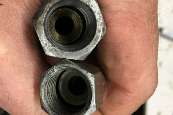
These examples highlight why it is vital to choose the right fitting based on your system’s requirements. The correct fitting not only ensures a leak-free connection but also maintains the necessary pressure levels for optimal performance. Choosing the right metric fitting can prevent operational inefficiencies, reduce maintenance costs, and ultimately extend the lifespan of your hydraulic system.

What Are Heavy-Duty Metric Fittings?

Definition and Characteristics

Heavy-duty metric fittings are robust hydraulic connectors specifically designed for demanding environments that require exceptional strength and resilience. These fittings are constructed to withstand extreme pressure conditions, making them ideal for applications where reliability is paramount. Engineered with reinforced walls and durable materials, heavy-duty metric fittings are built to handle the rigors of high-pressure fluid systems. Their enhanced structural integrity ensures that they can endure the physical stresses associated with heavy machinery and hydraulic systems, where pressure fluctuations, vibrations, and harsh operating conditions are the norm.

Heavy-duty metric fittings often comply with strict industry standards, ensuring consistency and performance across different systems and applications. The fittings are characterized by their ability to maintain a secure connection even under intense pressure, preventing leaks, bursts, or other system failures. Their design prioritizes durability, often making them larger and heavier than light-duty alternatives, which makes them suitable for hydraulic systems that demand long-lasting, reliable performance.

Key Features

Heavy-duty metric fittings are distinguished by several key features that make them ideal for high-stress applications:

Reinforced Walls: These fittings are designed with thicker walls compared to light-duty variants, allowing them to handle higher pressure levels without deforming or failing.

Superior Materials: Heavy-duty metric fittings are commonly made from high-strength materials like stainless steel, hardened alloys, and sometimes brass, chosen for their excellent corrosion resistance and strength. These materials can endure harsh conditions such as exposure to chemicals, moisture, and extreme temperatures.

Enhanced Pressure Resistance: Due to their construction, heavy-duty metric fittings are capable of withstanding significantly higher pressures, making them suitable for hydraulic systems that operate under extreme force.

Durability in Harsh Environments: Whether it’s operating in extreme cold, heat, or corrosive environments, heavy-duty fittings maintain their integrity over time, reducing the risk of failure in critical applications.

Applications

Heavy-duty metric fittings are vital in industries where hydraulic systems are subjected to constant high pressure and rough conditions. These fittings are a mainstay in the construction industry, used in equipment such as cranes, bulldozers, and excavators, where they ensure the hydraulic systems powering the machinery can perform reliably under heavy loads.

In the mining industry, where equipment must withstand extreme pressure and abrasive materials, heavy-duty metric fittings are employed in hydraulic drills, loaders, and conveyors, ensuring safe and uninterrupted operation.

Manufacturing industries also rely heavily on these fittings for hydraulic presses, molding machines, and other equipment where precise control and high pressure are required to shape or assemble materials. These applications highlight the critical role of heavy-duty metric fittings in maintaining the integrity and functionality of hydraulic systems in some of the most challenging environments.

What Are Light-Duty Metric Fittings?

Definition and Characteristics

Light-duty metric fittings are hydraulic connectors designed for systems that operate under lower pressure and lighter workloads. Unlike their heavy-duty counterparts, these fittings are built to meet the needs of less demanding environments where extreme pressure and harsh conditions are not a concern. Light-duty metric fittings are typically constructed with thinner walls, allowing them to handle moderate pressure levels efficiently. They are ideal for applications where system loads are lighter and the hydraulic connections do not experience the same intense stress as those in heavy-duty settings.

The materials used in light-duty metric fittings are generally more economical, such as standard steel, aluminum, or lighter alloys. These fittings still offer adequate strength and reliability for the environments they are designed for, but they are not meant to withstand the extreme forces or corrosive conditions found in heavy-duty applications. Instead, they provide a cost-effective and efficient solution for systems that do not require the rugged durability of more robust fittings.

Key Features

Light-duty metric fittings are defined by several characteristics that make them suitable for moderate hydraulic applications:

Thin-Wall Construction: The walls of light-duty metric fittings are thinner than those of heavy-duty fittings, which allows them to function effectively in systems with lower pressure while reducing material usage and cost.

Cost-Effectiveness: Because these fittings are typically made from more affordable materials and do not require the same level of reinforcement, they are a cost-efficient choice for businesses looking to balance performance with budget constraints.

Suitability for Non-Extreme Environments: Light-duty fittings are designed for applications where the hydraulic system is not exposed to extreme conditions such as high temperatures, corrosive chemicals, or excessive pressure fluctuations. They perform reliably in controlled environments where the system demands are predictable and less severe.

Applications

Light-duty metric fittings are commonly used in industries where hydraulic systems operate under moderate conditions, such as agriculture and automotive. In the agricultural industry, these fittings are often found in equipment like tractors, irrigation systems, and small hydraulic pumps, where pressure demands are lower, and the environment is generally less hostile compared to heavy industrial applications.

In automotive systems, light-duty fittings are used in fuel lines, braking systems, and fluid transfer systems, where precise control and moderate pressure are required. Additionally, light-duty metric fittings play a role in small-scale automation systems and light industrial machinery, where hydraulic power is needed for tasks like assembly, packaging, and material handling but without the intense demands of heavy industrial operations.

Comparing Heavy-Duty and Light-Duty Metric Fittings

Pressure Handling Capabilities

To clearly illustrate the differences in pressure handling between heavy-duty and light-duty metric fittings, the following comparison chart provides an overview of their respective pressure ratings:

Fitting Type

Pressure Rating Range

Heavy-Duty

6,000-10,000 PSI (414-690 bar)

Light-Duty

1,500-4,000 PSI(103 -276 bar)

This chart demonstrates that heavy-duty metric fittings are engineered to handle significantly higher pressure levels, making them suitable for high-pressure hydraulic systems found in demanding industrial applications. Light-duty fittings, on the other hand, are designed for moderate-pressure systems where lower forces are involved.

Material Strength and Durability

Heavy-duty and light-duty metric fittings differ not only in their pressure-handling capabilities but also in the materials used to construct them. Heavy-duty fittings are typically made from high-strength materials such as stainless steel, hardened alloys, and brass, which offer superior durability, corrosion resistance, and fatigue life. These materials are crucial for systems exposed to corrosive substances, extreme temperatures, or abrasive materials, as they prevent premature wear and reduce the likelihood of system failures.

Light-duty fittings, by contrast, are often made from aluminum, standard steel, or other lighter materials that, while adequate for lower-pressure systems, may lack the same level of corrosion resistance and durability. These materials are more suitable for environments that do not expose the fittings to harsh conditions, though they may require more frequent replacement as they degrade faster over time compared to heavy-duty options.

Cost Considerations

The cost of metric fittings can vary widely depending on their type, material, and application. Heavy-duty fittings tend to have a higher initial cost due to the superior materials and reinforced construction required to withstand high-pressure environments. However, this upfront investment is often offset by the fittings’ longer lifespan, reduced maintenance needs, and higher reliability in demanding applications. Over time, heavy-duty fittings may offer cost savings as they prevent costly system failures and reduce downtime.

Light-duty fittings, in contrast, are generally more cost-effective upfront due to their simpler construction and use of less expensive materials. However, because they are less durable and more susceptible to wear and tear, they may require more frequent replacements and higher maintenance costs over time, especially if used in systems that exceed their designed capabilities.

Weight and Space Requirements

Heavy-duty metric fittings tend to be larger and heavier than light-duty options due to their thicker walls and more robust construction. This added weight and bulk can be a consideration in systems where space is limited or where weight constraints are critical, such as in mobile equipment or aerospace applications. The additional size and weight may complicate system design, installation, and maintenance, requiring more careful planning to ensure that the fittings do not negatively impact the system’s overall efficiency.

Light-duty fittings, with their lighter weight and smaller dimensions, are better suited for compact systems or applications where space is a premium. Their lighter construction makes them easier to handle and install, and they take up less room in tight spaces. However, this advantage comes at the cost of reduced pressure-handling capabilities and durability.

Environmental and Application Suitability

When choosing between heavy-duty and light-duty metric fittings, it’s important to consider the environmental factors and application-specific conditions that may impact the performance of the fittings. Heavy-duty fittings are designed to excel in extreme environments where factors like temperature extremes, corrosive chemicals, and abrasive materials are common. Their construction from high-grade materials ensures that they can withstand these challenges without compromising the integrity of the hydraulic system.

Light-duty fittings, while adequate for moderate environments, may struggle in more extreme conditions. They are more vulnerable to corrosion, fatigue, and wear, especially when exposed to harsh substances or fluctuating temperatures. As a result, light-duty fittings are best suited for applications where the environment is controlled, and the hydraulic system is not subjected to extreme stresses.

Ultimately, the choice between heavy-duty and light-duty metric fittings should be based on a careful evaluation of the operating conditions, pressure requirements, and long-term cost implications for your specific hydraulic system.

Factors to Consider When Choosing

System Pressure Requirements

The most critical factor when deciding between heavy-duty and light-duty metric fittings is the pressure requirements of your hydraulic system. Hydraulic systems are designed to operate within specific pressure ranges, and the fittings you choose must be capable of handling those pressures without failure. Heavy-duty metric fittings are essential for systems that operate under high pressures, typically ranging between 6,000 to 10,000 PSI. These fittings are designed to maintain integrity under intense stress, preventing leaks or blowouts that could compromise system performance.

On the other hand, light-duty metric fittings are sufficient for systems operating at lower pressures (1,500 to 4,000 PSI), where the forces involved are less extreme. Installing the appropriate fitting for your system’s pressure needs is crucial to ensuring safe, efficient operation. Failure to select the right fitting could lead to pressure drops, system inefficiencies, or even catastrophic failures, potentially resulting in costly repairs and downtime.

Application-Specific Demands

metric hydraulic fitting different application Topa

Beyond pressure, the operational requirements of the specific machine or tool in question should heavily influence your fitting choice. Consider factors such as duty cycles, load stress, and vibration levels. For instance, a piece of machinery like a hydraulic excavator, which operates continuously under heavy loads, will benefit from the durability and strength of heavy-duty fittings. These fittings can withstand the repetitive stress and heavy-duty cycles that occur in such applications.

In contrast, for lighter machinery like small-scale agricultural equipment or automated tools with lower load requirements, light-duty fittings are often sufficient. The lower duty cycles and reduced load stress in these systems allow light-duty fittings to perform effectively without the need for the extra reinforcement found in heavy-duty variants. Evaluating the specific operational demands of your machinery is key to making the right choice between fitting types.

Budget and Long-Term Maintenance

Cost considerations are another important factor when selecting between heavy-duty and light-duty fittings. While heavy-duty fittings typically come with a higher initial cost due to the superior materials and robust construction, they offer significant advantages in terms of long-term durability and reduced maintenance. In harsh conditions or high-pressure environments, heavy-duty fittings can save money over time by reducing the need for frequent replacements, minimizing the risk of system failures, and preventing costly downtime.

On the other hand, light-duty fittings are generally more affordable upfront, making them an attractive option for systems with lower performance demands. However, they may require more frequent maintenance and replacement due to their lighter construction and lower pressure tolerance. When evaluating your budget, it’s important to balance the initial savings of light-duty fittings with the potential for higher long-term maintenance costs. If your system operates in a demanding environment, investing in heavy-duty fittings may lead to greater cost savings over the lifespan of your equipment.

Future Expansion and System Flexibility

When selecting fittings for your hydraulic system, it’s important to think about future expansion and system flexibility. Your current setup may meet today’s demands, but what if your system needs to handle higher pressures, larger loads, or additional components in the future? Heavy-duty fittings offer greater flexibility for future upgrades or system expansions because of their higher pressure tolerance and durability. By choosing fittings that can accommodate increased loads and pressures, you can ensure that your system remains adaptable to new requirements without needing to replace fittings later.

Light-duty fittings, while more cost-effective in the short term, may limit your system’s ability to scale up or adapt to new challenges. If future expansion is likely, investing in heavy-duty fittings from the start could save time and money in the long run, preventing the need for a system overhaul when increased demands arise.

In conclusion, selecting the right metric fittings requires careful consideration of your hydraulic system’s pressure requirements, application demands, budget, and future needs. By evaluating these factors, you can make an informed choice that ensures both short-term efficiency and long-term performance.

Conclusion

We recommend taking the time to assess your hydraulic system’s unique needs before committing to either heavy-duty or light-duty fittings. For personalized advice and further assistance, consulting with hydraulic experts can provide valuable insights tailored to your specific applications. If you need guidance or have any questions, our team of experts is here to help you make the right choice for your hydraulic system. Reach out to us for expert advice and support in selecting the best fittings for your requirements.

FAQ

Metric fittings are hydraulic connectors designed to join components like hoses and tubes, measured using the metric system (in millimeters) and often adhering to global standards like DIN or ISO.

Heavy-duty fittings are built for high-pressure, demanding environments, while light-duty fittings are suited for lower-pressure applications with lighter workloads.

Heavy-duty fittings should be used in applications that require handling high pressures, such as construction, mining, or manufacturing machinery.

No, light-duty fittings are not designed for high-pressure systems and may fail, leading to leaks or system breakdowns.

Yes, heavy-duty fittings are typically more expensive upfront due to their reinforced construction and durable materials, but they offer longer-term cost savings in harsh conditions.

Your choice should be based on your system’s pressure requirements, environmental conditions, and budget considerations. Consulting with a hydraulic expert can help you make the right decision.

Contact Topa

Have a question or suggestion? Fill out the form below to get in touch with one of our experts.

Choosing the Right Hydraulic Hose Ferrules

Choosing the Right Hydraulic Hose Ferrules

Choosing the Right Hydraulic Hose Ferrules

Table of Contents

Introduction

Typically made of metal, such as steel, stainless steel, or brass, ferrules are crimped onto the end of the hose to create a secure, leak-proof connection. Their primary function is to reinforce the hose and maintain its integrity under high pressure, ensuring that the assembly remains durable and reliable over time.

Understanding Hose Ferrules

What are Hose Ferrules?

Hose ferrules are metallic sleeves that play a crucial role in hydraulic hose assemblies, ensuring a secure and leak-proof connection between the hose and its fitting. Typically made from materials such as steel, stainless steel, brass, or aluminum, ferrules are crimped or pressed onto the end of a hose to anchor the fitting firmly in place. The crimping process compresses the ferrule onto the hose, ensuring that the hose and fitting remain locked together even under the extreme pressure and stress common in hydraulic systems. The ferrule’s primary purpose is to reinforce the hose, preventing it from pulling away from the fitting and ensuring a strong and durable connection.  

The key components of a ferrule include its shape, size, and function. Ferrules come in various shapes, often depending on the type of hose or fitting they are designed to be used with. The size of the ferrule must match the outer diameter of the hose to ensure a snug fit. Properly sized ferrules are critical to achieving a secure crimp and maintaining the integrity of the hose assembly. The function of the ferrule extends beyond just holding the hose and fitting together—it also provides strain relief and distributes the forces evenly across the connection, which is essential for preventing premature hose failure.

Common Applications of Hose Ferrules

Hose ferrules are used across various industries that rely on hydraulic systems to power machinery, move fluids, and ensure mechanical operations run smoothly. These industries include:

Construction: Hydraulic machinery such as excavators, bulldozers, and cranes rely heavily on hoses for fluid power transmission. Ferrules ensure the hoses used in these machines are secure and resistant to leaks, which is vital for maintaining the safety and performance of the equipment.

Manufacturing: Assembly lines and factory machinery frequently utilize hydraulic systems to move parts, press materials, and perform automated tasks. Ferrules are essential in these applications to maintain high pressure and continuous operation without failures.

Agriculture: Equipment such as tractors, harvesters, and plows use hydraulic hoses to operate various tools and attachments. In these demanding environments, ferrules help ensure that hoses remain intact despite exposure to extreme conditions like dirt, heat, and vibration.

Types of Hydraulic Ferrules

Hydraulic ferrules are essential components in hydraulic hose assemblies, connecting the hose to fittings securely and ensuring a leak-proof, reliable connection. Several types of hydraulic ferrules cater to different hose types and applications.  

Rubber Hydraulic Ferrule

Description: Rubber hydraulic ferrules are designed to suit R1AT/1SN 1-wire and R2AT/2SN 2-wire hoses, which are common in high-pressure hydraulic systems. These ferrules are essential for providing a strong, crimped connection between the rubber hose and the fitting. Additionally, multi-spiral non-skive ferrules are available to suit ISO/4SP/4SH multi-spiral hoses, which are typically used in more demanding applications requiring higher pressure and durability.

Applications: These ferrules are widely used in industrial equipment, construction machinery, and other heavy-duty hydraulic systems where high-pressure resistance is critical.

Thermoplastic Ferrule

Description: Thermoplastic ferrules are used for R7 and R8 thermoplastic hoses. These ferrules are specifically designed to accommodate the unique properties of thermoplastic hoses, which are more lightweight and flexible than traditional rubber hoses. They ensure a tight, secure fit while maintaining the flexibility of the hose.

Applications: Thermoplastic ferrules are commonly found in applications where low weight and flexibility are prioritized, such as mobile hydraulic equipment, robotics, and certain agricultural machinery.

Teflon Bore Ferrule

Description: Teflon bore ferrules are engineered to suit convoluted and smooth bore Teflon SS braid hoses. Teflon (PTFE) hoses are highly resistant to chemicals, heat, and corrosion, and are often used in environments where rubber or thermoplastic hoses would degrade. Teflon bore ferrules ensure that the hose remains securely attached to the fitting without compromising the integrity of the Teflon material.

Applications: These ferrules are ideal for industries such as pharmaceuticals, food and beverage, and chemical processing, where contamination, corrosion, and high-temperature resistance are paramount.

Common Types of Hydraulic Ferrules

00110

Description: The 00110 hydraulic hose ferrule is designed for SAE 100R1AT/EN8531SN hoses. These ferrules are typically used with single-wire braided hydraulic hoses, which are commonly employed in medium-pressure hydraulic applications. The 00110 ferrule is crimped onto the hose to secure it to the fitting, ensuring a strong, leak-free connection.

Applications: Medium-pressure hydraulic systems, such as those in agricultural machinery, construction equipment, and industrial machinery.

Topa 00110 Hose Ferrules

00110A

Description: The 00110A ferrule shares similarities with the 00110 but features an interior with vertical teeth. This design allows for deeper crimping during installation, achieving a better crimping effect that provides increased security and durability in the connection. The teeth create a stronger grip on the hose, minimizing the risk of slippage or leaks.

Applications: High-pressure applications where additional grip and crimping depth are required, such as in construction equipment and heavy-duty industrial machinery.

00210

Description: The 00210 ferrule is specifically designed for SAE 100R2AT or EN853 2SN hydraulic hoses, which are reinforced with two layers of wire braid. These ferrules are ideal for applications that demand higher pressure resistance compared to single-wire braided hoses. The 00210 ferrule ensures that the hose is securely attached to the fitting, preventing leaks under high pressure.

Applications: High-pressure hydraulic systems in construction, mining, and heavy equipment.

03310

Description: The 03310 ferrule is suitable for use with both one-wire and two-wire hydraulic hoses, offering versatility in various hydraulic applications. It provides a secure and reliable connection, ensuring that the hydraulic hose assembly can withstand the pressures and stresses encountered during operation.

Applications: Medium to high-pressure hydraulic systems in industrial machinery, agricultural equipment, and construction tools.

03310 Topa Hydraulic Hose Crimp Ferrule

00400

Description: The 00400 ferrule is designed for 4SP, 4SH, and R12 multi-spiral hoses. These hoses are used in extremely high-pressure applications where durability and reliability are paramount. The 00400 ferrules are engineered to handle the rigorous demands of these heavy-duty hoses, providing a solid, leak-proof connection.

Applications: Extremely high-pressure hydraulic systems, such as those in heavy machinery, cranes, and high-powered industrial equipment.

00621

Description: The 00621 ferrule is similar in appearance to the 00402 ferrule but is specifically designed for use with 6-layer hydraulic hoses, such as R13 and R15. These hoses are used in ultra-high-pressure applications that demand exceptional strength and durability. The ferrule ensures that the hose remains securely connected to the fitting, even under the extreme pressures encountered in these applications.

Applications: Ultra-high-pressure hydraulic systems in industries such as mining, oil and gas exploration, and heavy construction equipment.

00TF0

Description: The 00TF0 ferrule is designed for SAE 100R14 hydraulic hoses, which are often made of Teflon (PTFE). Unlike other ferrules, the interior of the 00TF0 ferrule is smooth and toothless, making it ideal for use with Teflon hoses that require a delicate yet secure connection. This ferrule is used where chemical resistance, high temperatures, and non-reactive properties are necessary.

Applications: Chemical processing, pharmaceutical manufacturing, food and beverage production, and other environments where Teflon hoses are required.

00TF0 Topa Hydraulic Hose Ferrule

00018

Description: The 00018 ferrule is designed for use with R7 and R8 thermoplastic hoses. These ferrules are engineered to accommodate the unique characteristics of thermoplastic hoses, which are known for their flexibility, lightweight nature, and abrasion resistance. The 00018 ferrule ensures a secure connection while maintaining the benefits of the thermoplastic hose.

Applications: Mobile hydraulic equipment, robotics, and low-weight applications where flexibility and abrasion resistance are important.

Key Considerations When Choosing Hose Ferrules

Selecting the right hose ferrules for a hydraulic system involves evaluating several factors to ensure the ferrule performs optimally under various conditions. The wrong choice can lead to system inefficiencies, leaks, or even catastrophic failure, so it’s essential to assess the following key considerations:

Hose Size and Compatibility

Importance of Selecting the Right Size for Your Hydraulic Hose:

Hose size is one of the most critical factors when choosing a ferrule. Ferrules must be sized correctly to match the outer diameter of the hose. If the ferrule is too large or too small, the connection may not hold properly, leading to potential leaks or disconnection under pressure.

Ensuring Compatibility Between Hose and Ferrule:

Compatibility between the hose and ferrule is crucial for maintaining the system’s integrity. For example, ferrules designed for thermoplastic hoses differ from those for rubber hydraulic hoses. Ensuring that the ferrule type matches the hose material and construction will prevent premature wear, leaks, and failure during operation.

Pressure Ratings

Understanding Pressure Ratings and Selecting Ferrules That Can Withstand the Operating Pressure of Your System:

Every hydraulic system operates within specific pressure ranges. When selecting ferrules, it’s essential to know the maximum operating pressure of your system and choose ferrules that are rated to handle this pressure. For example, multi-spiral hose ferrules are designed for high-pressure systems, while ferrules for thermoplastic hoses may have lower pressure ratings.

Consequences of Choosing a Ferrule with Insufficient Pressure Rating:

If the ferrule is not rated for the system’s pressure, it may fail, causing a rupture or leak in the hydraulic hose. This can lead to downtime, costly repairs, and in some cases, hazardous situations for equipment operators. Always ensure the ferrule’s pressure rating meets or exceeds the maximum operating pressure of the system.

Environmental Factors

Evaluating Temperature Extremes, Exposure to Chemicals, and Other Environmental Considerations When Selecting Ferrules:

Environmental factors such as temperature fluctuations, exposure to chemicals, moisture, and UV light can affect the performance and longevity of hose ferrules. Stainless steel or Teflon ferrules may be required for systems exposed to corrosive environments, while rubber ferrules may work well in general-purpose applications.

Temperature extremes can also impact ferrules. In high-temperature environments, Teflon bore ferrules are ideal, whereas in sub-zero temperatures, special materials designed to maintain flexibility and strength are necessary.

Flexibility Needs

Ensuring That the Ferrule Meets the Flexibility Requirements of the Hose Assembly:

Different applications require varying levels of hose flexibility. Some ferrules are designed to accommodate hoses that need to bend or flex during operation, such as those used in mobile equipment or robotics. Choosing a ferrule that supports the necessary range of motion will prevent fatigue in the hose and ensure that the system performs as expected.

If a system requires high flexibility, such as in tight spaces or moving machinery, ferrules must not restrict the horse’s movement. Thermoplastic or push-on ferrules are often used in applications where flexibility is a key requirement.

Crimping Specifications and Standards

Reviewing Manufacturer Specifications for Crimping and Adherence to Industry Standards:

Proper crimping is essential to achieving a secure connection between the hose and the ferrule. Each ferrule and hose combination requires specific crimping tools and procedures to ensure that the ferrule is attached correctly. Review manufacturer specifications for crimping, including crimp diameters, compression force, and tools recommended for each type of ferrule.

Adherence to industry standards, such as ISO or SAE, ensures that the ferrule and hose assembly meet the necessary safety and performance requirements. Working with certified equipment and following best practices reduces the risk of system failure.

Importance of Proper Crimping to Avoid Leakage or Damage to the Hose Assembly:

Improper crimping can result in a weak connection that leads to leaks or even hose blowouts under pressure. Over-crimping may damage the hose or ferrule, while under-crimping can lead to insufficient grip on the hose, causing it to loosen during operation. Regularly inspect crimped connections for wear, and ensure that crimping is done according to manufacturer guidelines to avoid costly failures.

Conclusion

Whether you’re dealing with extreme temperatures, chemical exposure, or high-pressure requirements, choosing the correct ferrule material and type can significantly impact the overall efficiency and reliability of your hydraulic system. By taking the time to make informed decisions, you help to ensure that your equipment runs smoothly and efficiently, reducing the risk of premature wear and unexpected breakdowns.

FAQ

A hose ferrule is used to secure the hydraulic hose to its fitting, ensuring a leak-proof, durable connection in a hydraulic system.

The ferrule size must match the outer diameter of the hose. Always check the manufacturer’s specifications to ensure proper compatibility.

No, ferrules are typically designed for specific hose types (e.g., rubber, thermoplastic, Teflon). Always choose a ferrule that matches the material and construction of your hose.

Using the wrong ferrule can result in leaks, hose damage, or even system failure, leading to costly repairs and downtime.

Regular inspections are recommended, especially during routine maintenance, to check for signs of wear, corrosion, or improper crimping.

Yes, proper crimping is crucial for a secure connection. It’s recommended to have ferrules crimped with professional-grade tools and to follow the manufacturer’s guidelines for best results.

Contact Topa

Have a question or suggestion? Fill out the form below to get in touch with one of our experts.

Hose Ferrule Installation Common Mistakes to Avoid

Hose Ferrule Installation: Common Mistakes to Avoid

Hose Ferrule Installation: Common Mistakes to Avoid

Table of Contents

Introduction

When done correctly, it not only ensures that the system functions smoothly but also plays a vital role in preventing leaks, which can lead to costly downtime and potential safety hazards. The installation process might seem straightforward, but even minor mistakes can result in significant issues, from reduced hose life to catastrophic system failures. In this post, we will delve into the most common mistakes made during hose ferrule installation, providing you with practical insights to avoid them.

Preparation Before Installation

Proper Hose Selection

Hose Compatibility:

Choosing the right hose for the ferrule is crucial to ensure a secure and leak-free connection. The ferrule and hose must be compatible in terms of size, type, and material. Using an incompatible hose can lead to improper fitting, which increases the risk of hose failure and leaks. For instance, a ferrule designed for a specific type of hydraulic hose may not perform well with another type, even if it appears similar. Understanding the specific requirements of your system and selecting hoses that meet these needs will significantly enhance the performance and reliability of your installation.

Checking Hose Specifications:

To ensure proper compatibility, it is essential to verify the hose’s specifications before installation. This includes measuring the hose’s diameter and length to match the ferrule’s dimensions. Additionally, checking the hose’s pressure rating is critical to ensure it can handle the operating pressures of your system. Incorrect dimensions or pressure ratings can compromise the integrity of the connection, leading to potential failures. Using manufacturer guidelines and detailed specifications for both the hose and ferrule will help you make the right choice and ensure a secure, reliable installation.

Tool Selection

Hydraulic Hose cut machine

Crimping Tools:

Selecting the appropriate crimping tool is vital for achieving a proper and secure crimp. Crimping tools come in various types, such as manual, hydraulic, and electric, each suited for different applications and hose sizes. The tool must match the ferrule and hose size to ensure consistent pressure is applied during crimping. An incorrect or inadequate tool can lead to over-crimping or under-crimping, which affects the performance of the hose connection. Investing in high-quality crimping tools and regularly maintaining them will help achieve precise and reliable crimping results.

Inspection Tools:

After crimping, it is important to inspect the ferrule placement and crimp quality to ensure that the installation is up to standard. Inspection tools such as micrometers, calipers, and specialized crimp gauges can help verify the dimensions and crimping quality. These tools enable you to check for proper alignment, ensure that the ferrule is evenly crimped around the hose, and confirm that there are no gaps or inconsistencies. Regular inspection using these tools helps identify any issues early, reducing the risk of leaks and enhancing the overall reliability of the hose assembly.

Common Mistakes During Hose Ferrule Installation

Incorrect Ferrule Size

Oversized Ferrules: Using ferrules that are too large for the hose can lead to a poor fit and inadequate compression. This mismatch can cause the ferrule to slip, resulting in leaks or even complete disconnection under pressure. Additionally, oversized ferrules can compromise the strength of the hose connection, potentially leading to hose blowouts or system failures.

Undersized Ferrules: Ferrules that are too small can cause excessive stress on the hose material and may not crimp tightly enough to ensure a secure fit. This can lead to leaks, reduced hose performance, and premature wear. An undersized ferrule may also fail to adequately hold the hose in place, resulting in operational issues and potential damage to the system.

Improper Hose Insertion

Partial Insertion: If the hose is not fully inserted into the ferrule, it can create a weak connection that is prone to failure. Partial insertion can cause leaks at the ferrule interface and may lead to hose slippage or detachment under pressure. Ensuring that the hose is fully inserted into the ferrule is crucial for creating a secure and reliable connection.

Misalignment: Crooked or angled insertion of the hose into the ferrule can result in uneven crimping, which compromises the integrity of the connection. Misalignment can cause stress concentrations, leading to leaks or hose damage. Proper alignment ensures that the ferrule compresses evenly around the hose, providing a stable and leak-proof connection.

Incorrect Crimping Technique

Over-crimping: Crimping the ferrule too tightly can damage the hose, causing deformation or internal hose failure. Over-crimping can also lead to a reduction in the flexibility of the hose, which may impact the system’s performance and cause premature wear. It is important to follow the manufacturer’s specifications for crimping pressures to avoid over-crimping.

Under-crimping: An insufficient crimp can result in a loose fit that is prone to leaks and can cause the ferrule to slip or move. Under-crimped connections are less durable and may fail under operational pressures, leading to system failures and potential safety hazards. Ensuring proper crimping pressure is essential for a secure and long-lasting connection.

Crimp Positioning: Placing the crimp in the correct position on the ferrule is crucial for a secure fit. Incorrect crimp positioning can result in uneven compression and an inadequate seal, leading to leaks and potential failures. Proper crimping technique involves ensuring that the crimp is evenly applied around the ferrule and positioned correctly according to the manufacturer’s guidelines.

Neglecting to Deburr or Clean the Hose End

Sharp Edges: Leaving sharp edges on the hose end after cutting can damage the ferrule or the internal components of the hose. Sharp edges can create stress points that lead to leaks or premature wear. It is important to deburr the hose end to ensure a smooth surface that facilitates proper insertion into the ferrule.

Contamination: Contaminants on the hose end, such as dirt, oil, or metal shavings, can interfere with the crimping process and lead to weak connections. Contamination can also cause corrosion or degradation of the ferrule and hose materials. Thoroughly cleaning the hose end before installation helps prevent these issues and ensures a secure and reliable connection.

Detailed Steps for Correct Ferrule Installation

StStep 1: Inspect the Hose and Ferrule

Visual Inspection: Begin by thoroughly examining both the hose and the ferrule for any visible defects or damage. Look for signs of wear, cracks, or deformation on the hose and ferrule. Any imperfections can compromise the integrity of the installation and should be addressed before proceeding.

Measurement Verification: Measure the hose and ferrule dimensions to ensure they meet the manufacturer’s specifications. This includes checking the hose’s outer diameter and the ferrule’s inner diameter to confirm compatibility. Accurate measurements are crucial to ensure a proper fit and avoid issues such as leaks or inadequate compression.

Step 2: Prepare the Hose End

Cutting the Hose: Use a clean, sharp cutting tool to cut the hose to the correct length. Ensure the cut is straight and perpendicular to the hose axis to prevent uneven insertion into the ferrule. Avoid using tools that can cause fraying or deformation of the hose ends.

Deburring the Edge: After cutting, smooth out any sharp edges or burrs on the hose end using a deburring tool or file. This step is essential to prevent damage to the ferrule and to ensure a smooth and clean surface for a secure connection. Properly deburred edges help achieve a tight, leak-proof seal.

Hydraulic Hose Assembly cut hose

Step 3: Insert the Hose into the Ferrule

Ensuring Full Insertion: Carefully insert the hose into the ferrule, making sure it is pushed to the end. Use techniques such as rotating the hose slightly or applying a gentle push to ensure full insertion. The hose should be flush with the ferrule’s end to achieve proper crimping.

Checking Alignment: Verify that the hose is straight and properly aligned within the ferrule. Misalignment can lead to uneven crimping and potential leaks. Use alignment tools or visual checks to ensure that the hose is centered and straight throughout its length.

Step 4: Crimp the Ferrule

Crimping Process: Follow the manufacturer’s guidelines for crimping the ferrule. Place the ferrule with the hose inserted into the crimping tool and apply the specified crimping pressure. Ensure that the crimping tool is correctly adjusted to achieve the proper crimp size and compression. Maintain steady and even pressure during crimping to avoid over-crimping or under-crimping.

Crimp Inspection: After crimping, inspect the ferrule to ensure it is securely compressed around the hose. Check for uniform crimping around the ferrule and ensure that it is properly positioned. Look for any signs of uneven crimping or deformation, and verify that the crimp meets the specified dimensions and requirements.

Step 5: Post-Installation Inspection

Visual and Physical Inspection: Perform a final visual inspection to check for leaks, proper alignment, and a secure fit. Ensure that the ferrule is properly seated on the hose and that there are no visible defects or issues. Physically inspect the connection by applying gentle pressure or flexing the hose to confirm stability.

Pressure Testing: Conduct a pressure test to verify the success of the installation. This test involves applying pressure to the hose assembly to ensure it can withstand the operational pressures without leaking or failing. Follow the manufacturer’s recommended pressure testing procedures and record the results to confirm the integrity of the installation.

Troubleshooting Common Installation Issues

Leaks After Installation

Potential Causes: Leaks after installation can arise from several factors. Common causes include improper ferrule size, incomplete hose insertion, or incorrect crimping. Other potential issues are damage to the hose or ferrule during installation, contamination, or the use of incompatible components.

Solutions: To troubleshoot and fix leaks, first, inspect the hose and ferrule connection for visible signs of leakage. Check the ferrule size and ensure it matches the hose specifications. Verify that the hose is fully inserted into the ferrule and that crimping was performed correctly. Re-crimping the ferrule with proper pressure might resolve the issue. If contamination or damage is detected, replace the affected components and clean the area thoroughly. Conduct a pressure test to confirm that the leak has been resolved.

Crimping Machine Malfunctions

Common Machine Errors: Crimping machines can experience various issues, such as incorrect crimping pressure, inconsistent crimp sizes, or mechanical failures. Common machine errors include calibration problems, worn-out dies, and hydraulic pressure inconsistencies.

Troubleshooting Tips: To resolve crimping machine issues, start by checking and recalibrating the machine according to the manufacturer’s specifications. Inspect the crimping dies for wear and replace them if necessary. Ensure that the hydraulic system is functioning correctly and that pressure settings are accurate. Regular maintenance and calibration checks can prevent many common machine errors. If problems persist, consult the machine’s manual or contact technical support for further assistance.

Hose Slippage

Causes of Slippage: Hose slippage within the ferrule can occur due to several reasons, including improper ferrule size, insufficient crimping pressure, or incomplete hose insertion. Slippage can also result from using the wrong type of ferrule or hose material that does not fit well together.

Preventative Measures: To prevent and fix hose slippage, ensure that the ferrule size is correct and compatible with the hose. Verify that the hose is fully inserted into the ferrule before crimping. Use the appropriate crimping pressure as specified by the manufacturer to achieve a secure fit. Regularly inspect the ferrule and hose connections for signs of wear or damage. If slippage is detected, re-crimp the ferrule to the correct specifications or replace the ferrule if it is worn or damaged.

Conclusion

In this post, we’ve covered essential aspects of hose ferrule installation and highlighted common mistakes to avoid. If you find yourself uncertain about any aspect of the installation process or if you encounter persistent issues, don’t hesitate to seek professional assistance. Experts can provide valuable insights and help ensure that your hydraulic systems are installed correctly and operate efficiently. If you found this guide helpful, please share it with your colleagues or industry peers who might benefit from these insights.

FAQ

A hose ferrule is a metal component used to secure the hose to a fitting. It is crucial for maintaining a tight seal and ensuring that the hose does not slip or leak under pressure. Proper installation of the ferrule ensures system integrity, prevents leaks, and extends the hose’s lifespan.

Choose a ferrule that matches the hose’s diameter and pressure rating. Check the manufacturer’s specifications for compatibility to ensure a proper fit. An oversized or undersized ferrule can lead to leaks or hose damage.

You will need a crimping tool to compress the ferrule onto the hose, along with inspection tools to verify correct placement and crimp quality. Ensure that all tools are in good working condition and suitable for the hose and ferrule sizes being used.

To prevent leaks, ensure the hose is fully inserted into the ferrule and that the ferrule is crimped correctly. Verify that the crimping pressure is within the recommended range and check for any visible signs of damage or contamination before installation.

If the crimping machine is not working properly, check for common issues like calibration problems, worn-out dies, or hydraulic pressure inconsistencies. Recalibrate the machine, replace worn components, and ensure that the hydraulic system is functioning correctly. Consult the machine’s manual or seek technical support if needed.

Prevent hose slippage by ensuring that the ferrule size is correct and that the hose is fully inserted into the ferrule before crimping. Use the appropriate crimping pressure as specified by the manufacturer. Regularly inspect the connections for wear or damage and re-crimp or replace components if necessary.

Contact Topa

Have a question or suggestion? Fill out the form below to get in touch with one of our experts.

Top 5 Signs Your Hose Ferrule Needs Replacement

Top 5 Signs Your Hose Ferrule Needs Replacement

Top 5 Signs Your Hose Ferrule Needs Replacement

Table of Contents

Introduction

The constant exposure to high pressures, fluctuating temperatures, and harsh operating environments can cause ferrules to degrade. This degradation can manifest in various forms, such as cracks, corrosion, or deformation, compromising the ferrule’s ability to maintain a secure connection. When a ferrule begins to wear, it can lead to leaks, reduced efficiency, and ultimately, system failure. The impact of ferrule degradation on hydraulic system performance is significant, as it can disrupt fluid flow, reduce system pressure, and cause premature wear on other components.

Sign 1: Visible Cracks or Damage on the Ferrule  

Causes of Physical Damage

Common Causes

External Impacts: One of the most common causes of visible cracks or damage to ferrules is external impact. This could occur during the transportation, handling, or installation of hydraulic hoses. Ferrules, being the protective outer layer for the hose ends, can be damaged if struck by heavy objects or if dropped, leading to visible cracks or dents. Such impacts may not only affect the ferrule but also compromise the integrity of the hose underneath.

Pressure Surges: Hydraulic systems often operate under high pressure, varying significantly depending on the application. Sudden spikes in pressure, known as pressure surges, can exert excessive force on the ferrule. Over time, this repeated stress can cause micro-cracks that gradually expand, leading to visible damage. Pressure surges are particularly problematic in systems with poor pressure regulation or inadequate maintenance.

Mechanical Wear: The constant movement and flexing of hydraulic hoses during operation can lead to mechanical wear on the ferrules. This wear is more pronounced in systems where hoses are subjected to frequent bending, twisting, or vibration. Over time, this wear can manifest as cracks or thinning of the ferrule material, especially at points where the hose is most stressed.

hose Ferrule fail

Installation Issues

Improper Installation: Incorrect installation of ferrules is another significant cause of visible damage. If the ferrule is not correctly aligned or is crimped with too much or too little force, it can lead to uneven stress distribution. This uneven stress can cause the ferrule to crack under pressure or during hose movement. Additionally, if the ferrule is not properly secured, it may shift or loosen over time, leading to further damage.

Material Compatibility: Using ferrules made from materials that are not compatible with the hose or the hydraulic fluid can also cause damage. For example, a ferrule that is too rigid or brittle for a particular hose material may crack more easily under normal operating conditions. Ensuring that the ferrule material is compatible with the hose and the system’s operating conditions is crucial for preventing damage.

Installation Issues

Risks of Operating with Damaged Ferrules

Leaks: One of the most immediate risks of operating with damaged ferrules is the potential for leaks. Cracks or deformations can break the seal between the hose and the fitting, allowing hydraulic fluid to escape. Even a small leak can lead to significant fluid loss over time, reducing the efficiency of the hydraulic system and potentially causing environmental contamination.

Hose Blowouts: In more severe cases, operating with a cracked or damaged ferrule can lead to a hose blowout. A blowout occurs when the hose completely fails, often accompanied by a sudden release of hydraulic fluid at high pressure. This can not only cause extensive damage to the hydraulic system but also pose serious safety hazards to operators and nearby equipment.

System Failure: Over time, the stress on a damaged ferrule can cause it to fail, leading to a loss of pressure in the hydraulic system. This can result in system failure, where the entire hydraulic operation comes to a halt. The downtime and repair costs associated with such failures can be significant, especially in industrial settings where hydraulic systems are critical to operations.

Sign 2: Leaking Hydraulic Fluid

Understanding the Connection Between Leaks and Ferrule Condition

Leak Causes

Worn or Damaged Ferrules: One of the primary causes of hydraulic fluid leaks is the deterioration or damage of ferrules. Over time, ferrules can wear out due to constant pressure, exposure to harsh environments, or the natural aging of materials. When ferrules become worn or cracked, they can no longer maintain a secure seal between the hose and the fitting. This compromised seal allows hydraulic fluid to escape, leading to leaks.

Pressure Variations: Hydraulic systems often operate under high pressure, and any variation in this pressure can exacerbate wear on the ferrules. For instance, sudden pressure spikes or continuous operation at maximum pressure levels can stress the ferrule material, accelerating its degradation and increasing the likelihood of leaks.

Ferrule Integrity

Importance of Ferrule Quality: The effectiveness of the hose coupling largely depends on the integrity of the ferrule. A high-quality ferrule is designed to withstand the operational demands of hydraulic systems, maintaining a tight seal under pressure. However, even the best ferrules are subject to wear over time, especially in demanding environments. If the ferrule’s integrity is compromised, it can no longer function effectively, leading to leaks.

Coupling Effectiveness: The connection between the hose and the fitting is crucial for preventing leaks. Ferrules play a vital role in securing this connection. Any deterioration in the ferrule’s condition directly impacts the coupling’s effectiveness, making the system more susceptible to leaks. Ensuring that ferrules are in good condition is essential for maintaining the overall integrity of the hydraulic system.

Impact of Hydraulic Fluid Leaks

Equipment Damage

Wear and Corrosion: Hydraulic fluid leaks can cause significant damage to equipment. When fluid escapes from the system, it can come into contact with other components, leading to wear and corrosion. Over time, this can weaken the affected parts, causing them to fail prematurely. In addition to the immediate damage, leaks can also lead to the contamination of hydraulic fluid, further degrading system performance.

Reduced Efficiency: Leaks reduce the amount of hydraulic fluid available to power the system, leading to a drop in efficiency. This can result in slower operation, reduced power output, and increased strain on the remaining fluid and components. If left unchecked, leaks can cause a domino effect, leading to more extensive system failures and costly repairs.

Environmental and Cost Implications

Environmental Hazards: Hydraulic fluid is often hazardous to the environment. Leaks can lead to the contamination of soil, water sources, and other natural resources. In industrial settings, this can result in significant environmental damage, leading to fines, cleanup costs, and potential legal liability. Preventing leaks through regular inspection and maintenance of ferrules is not only a safety measure but also an environmental responsibility.

Costly Cleanups and Repairs: Beyond the environmental impact, fluid leaks can be expensive to clean up. The cost of repairing the damage caused by leaks, replacing lost fluid, and restoring contaminated areas can quickly add up.

Sign 3: Corrosion or Rust on the Ferrule

Causes of Ferrule Corrosion

Environmental Factors

Exposure to Moisture: One of the primary environmental factors contributing to ferrule corrosion is exposure to moisture. Hydraulic systems often operate in environments where water, humidity, or condensation is present. Over time, this moisture can penetrate the protective layers of the ferrule, leading to the formation of rust. In particular, systems used outdoors or in damp environments are more susceptible to corrosion.

Chemicals and Harsh Environments: Hydraulic systems used in industrial or agricultural settings may be exposed to a variety of chemicals, such as fertilizers, pesticides, or industrial solvents. These chemicals can react with the metal of the ferrule, accelerating the corrosion process. Additionally, ferrules used in marine environments are particularly vulnerable to corrosion due to the presence of saltwater, which is highly corrosive to most metals.

Temperature Fluctuations: Significant temperature changes can also contribute to ferrule corrosion. In environments where hydraulic systems are exposed to extreme heat or cold, the metal ferrules can expand and contract. This thermal cycling can create micro-cracks in the protective coating, allowing moisture and chemicals to penetrate and corrode the underlying metal.

Material and Coating

Material Selection: The material from which a ferrule is made plays a critical role in its resistance to corrosion. Ferrules made from stainless steel or other corrosion-resistant alloys tend to last longer in harsh environments compared to those made from plain steel or lower-grade metals. However, the cost of these materials can be higher, so it’s essential to balance cost with the specific needs of the application.

Protective Coatings: The application of protective coatings, such as zinc plating, anodizing, or powder coating, can significantly enhance the corrosion resistance of ferrules. These coatings act as a barrier, preventing moisture, chemicals, and other corrosive elements from reaching the metal surface. However, the effectiveness of these coatings can diminish over time, especially if the coating is scratched, chipped, or worn away. Regular inspection of the coating integrity is essential to ensure continued protection.

Hose Ferrule rust

Risks of Corroded Ferrules

Weakened Ferrules

Compromised Strength: Corrosion significantly weakens ferrules by eating away at the metal, reducing its thickness and structural integrity. As the ferrule corrodes, it becomes less capable of maintaining a secure connection between the hose and the fitting. This compromised strength can lead to a variety of problems, including leaks, pressure loss, and ultimately, system failure.

Increased Likelihood of Leaks: A corroded ferrule is much more likely to develop leaks. As the metal deteriorates, it can no longer form a tight seal, allowing hydraulic fluid to escape. These leaks not only reduce the efficiency of the hydraulic system but can also lead to contamination of the environment and increased operational costs.

Sign 4: Difficulty in Fitting or Removal

Reasons for Difficulty in Ferrule Handling

Wear and Tear

Deformation from Use: Over time, the constant stress and strain placed on hydraulic systems can lead to wear and tear on ferrules. This wear is particularly evident in systems that experience frequent movement, high pressure, or vibration. As ferrules age, they may begin to deform, making them more difficult to fit onto hoses or remove from fittings. Deformation can result in the ferrule losing its original shape, which is essential for a proper seal. When a ferrule becomes misshapen, it can be nearly impossible to fit it correctly onto a hose or remove it without damaging the hose or the ferrule itself.

Material Fatigue: Repeated cycles of pressure changes and physical stresses can also cause material fatigue, where the ferrule’s metal becomes less resilient. This can lead to small cracks, dents, or even slight expansions that make the ferrule harder to handle. Once the material starts to fatigue, the ferrule may not align correctly with the hose, leading to difficulties during both fitting and removal.

Misalignment

Causes of Misalignment: Misalignment of ferrules can occur due to improper installation, uneven crimping, or physical damage during use. When a ferrule is not perfectly aligned with the hose or fitting, it can cause significant issues during installation or removal. Even a slight misalignment can make it difficult to achieve the proper seal, leading to frustration during maintenance or repair efforts.

Impact of Misalignment: Misaligned ferrules are not only harder to fit or remove, but they also pose a risk of damaging the hose or the fitting. Forcing a misaligned ferrule into place can create additional stress on the connection points, leading to leaks or even catastrophic failure. Proper alignment is crucial for ensuring that the hydraulic system operates efficiently and safely.

Consequences of Ignoring Fitment Issues

System Inefficiencies

Leaks and Pressure Drops: One of the most common consequences of poor ferrule fitment is the occurrence of leaks. A ferrule that doesn’t fit properly can’t create the necessary seal, allowing hydraulic fluid to escape. Even small leaks can result in significant pressure drops, reducing the system’s efficiency and increasing operational costs. Over time, these leaks can also lead to environmental contamination and require extensive cleanup efforts.

Increased Wear on Components: Improper fitment can cause uneven pressure distribution within the hydraulic system, leading to increased wear on other components. This can result in premature failure of hoses, fittings, or even the hydraulic pump itself. Addressing fitment issues early on can help prevent these inefficiencies and extend the life of the system.

Safety Concerns

Risk of Hose Failure: A poorly fitted ferrule can compromise the integrity of the hose, increasing the risk of hose failure. If the ferrule is not securely attached, it may come loose under pressure, leading to a sudden release of hydraulic fluid. This can cause the hose to whip violently, posing a significant danger to anyone nearby and potentially damaging surrounding equipment.

Potential for Injury: Mishandling ferrules during installation or removal can also lead to injury. If a ferrule is difficult to fit or remove, there’s a higher chance of operators using excessive force or improper tools, increasing the risk of slips, cuts, or other injuries. Additionally, a failed ferrule under pressure can lead to high-pressure fluid ejection, which is a serious safety hazard.

System Shutdowns: In severe cases, fitment issues can lead to system shutdowns. If a ferrule fails during operation, the hydraulic system may need to be stopped for emergency repairs, leading to costly downtime. In industrial settings, such shutdowns can have significant financial implications, especially if they occur frequently due to neglected fitment issues.

Sign 5: Unusual Noises During Operation

Identifying Unusual Noises

Types of Noises

Hissing Sounds: One of the most common noises indicating a problem with ferrules is a hissing sound. This noise typically suggests that there is a leak somewhere in the hydraulic system. When ferrules become worn, cracked, or improperly fitted, they can allow hydraulic fluid to escape under pressure, creating a hissing noise. This sound may be continuous or intermittent, depending on the severity of the leak and the pressure within the system.

Whining Sounds: A whining noise during operation can also signal issues with ferrules. This type of noise is often associated with increased friction within the hydraulic system, which can occur if ferrules are misaligned or damaged. The increased resistance can cause the system to work harder, leading to a whining sound as the fluid struggles to flow smoothly through the system.

Clunking Sounds: Clunking or knocking sounds during operation may indicate that a ferrule has become loose or that there is significant misalignment within the system. These noises can result from the movement of loose components that should be securely fixed. When ferrules are not properly seated or have been compromised by wear or damage, they may shift during operation, leading to these disturbing sounds.

Impact on Noise Levels

Ferrule Wear and Noise: As ferrules wear over time, their ability to maintain a secure and tight connection diminishes. This degradation can lead to gaps or misalignments, which disrupt the smooth operation of the hydraulic system. These disruptions often manifest as unusual noises that can vary in intensity and frequency depending on the extent of the wear and the specific conditions of the system.

Noise as an Early Warning: Unusual noises are often one of the earliest indicators of a problem within the hydraulic system, particularly with ferrules. Paying attention to these sounds and addressing them promptly can prevent more severe issues from developing. Operators should be trained to recognize and respond to changes in noise levels during system operation as part of a proactive maintenance strategy.

Common Causes of Noises

Loose or Damaged Ferrules

Gaps and Misalignments: When ferrules become loose or sustain damage, they can no longer maintain the precise fit required for efficient system operation. This can create gaps between the hose and fitting, leading to fluid leaks and pressure fluctuations. As the hydraulic fluid forces its way through these gaps, it can generate hissing or whining sounds. Additionally, the misalignment of ferrules can cause parts of the system to rub against each other, producing clunking noises as components move out of sync.

Vibration and Movement: Loose ferrules can also exacerbate vibrations within the hydraulic system. These vibrations can cause metal components to knock against each other, producing clunking or rattling noises. Over time, this can lead to further damage, not only to the ferrules but also to other parts of the system, increasing the risk of a catastrophic failure.

Other Causes

Pressure Fluctuations: Hydraulic systems operate under high pressure, and any fluctuation in this pressure can lead to unusual noises. Ferrules that are not adequately sealed can cause pressure drops, resulting in hissing sounds as fluid escapes or as the system compensates for the loss of pressure. This can also cause the hydraulic pump to work harder, leading to whining noises.

Component Wear: While ferrule wear is a common cause of unusual noises, it’s important to consider that other components in the hydraulic system may also contribute to these sounds. Worn hoses, fittings, or seals can also lead to similar noises, and it’s essential to conduct a thorough inspection to identify the exact source of the problem. However, since ferrules are critical points of connection, they should be one of the first components checked when unusual noises are detected.

Conclusion

Each of these signs points to potential weaknesses in your hydraulic connections that, if left unaddressed, could lead to significant operational failures and costly downtime. By staying vigilant and addressing any signs of wear or damage early on, you can avoid unexpected breakdowns, minimize repair costs, and extend the life of your equipment.

FAQ

A ferrule is a small metal sleeve crimped onto the end of a hydraulic hose to secure the fitting and create a tight, leak-free seal.

Replace a ferrule if you notice visible cracks, leaks, rust, difficulty fitting or removing the ferrule, or if you hear unusual noises during system operation.

Hose ferrules can wear out due to regular use, exposure to harsh environments, pressure surges, improper installation, and physical damage.

Yes, you can replace a ferrule yourself if you have the right tools and follow proper safety procedures. However, for complex systems, it may be best to seek professional help.

It’s recommended to inspect ferrules regularly, especially before and after heavy use, or at least during routine maintenance checks.

You can purchase high-quality replacement ferrules from specialized hydraulic equipment suppliers, online stores, or directly from manufacturers. For assistance, contact our team.

Contact Topa

Have a question or suggestion? Fill out the form below to get in touch with one of our experts.

Hydraulic Hose Color Coding, Ferrules, and Skiving

Hydraulic Hose: Color Coding, Ferrules, and Skiving

Hydraulic Hose Detail: Color Coding, Ferrules, and Skiving

Table of Contents

Introduction

Hydraulic hoses serve as the conduits for transferring fluid power, enabling complex systems to function efficiently and reliably. However, the performance and safety of hydraulic systems hinge not just on the hoses themselves, but also on a deeper understanding of the various elements that make up these systems—such as color coding, ferrules, and skiving. In this post, we will delve into the intricacies of hydraulic hose color coding, the vital role of ferrules, and the technical process of skiving.

Understanding Hydraulic Hose Color Coding

Purpose of Color Coding

Facilitates Quick and Accurate Identification of Hoses:

Color coding serves as a visual cue that helps operators and maintenance personnel quickly identify specific hoses. This is particularly useful in complex systems where multiple hoses are used, each carrying different fluids or operating under different pressures.

Enhances Safety by Reducing the Risk of Incorrect Connections:

By clearly distinguishing between hoses, color coding reduces the likelihood of incorrect connections. This is vital in preventing cross-contamination of fluids or accidental connection to a high-pressure line, both of which could lead to system failure or safety hazards.

Colors coding

Common Industry Standards

Overview of Standard Color Codes Used in the Industry:

The hydraulic industry typically follows standardized color codes to maintain consistency and ensure that hoses can be easily identified across different systems and applications. For example:

Red: Often used to indicate high-pressure lines.

Blue: Typically denotes low-pressure return lines.

Yellow: This may be used for fluid lines carrying specific types of oil or hydraulic fluid.

Explanation of What Each Color Typically Represents:

Each color within the coding system usually corresponds to a particular characteristic of the hose, such as:

Pressure Rating: Color coding helps identify hoses that are rated for specific pressure ranges, ensuring they are used correctly in high or low-pressure applications.

Fluid Type: Different colors might indicate the type of fluid carried by the hose, such as hydraulic oil, coolant, or air, helping to prevent cross-contamination and ensure the proper fluid is used for the right application.

Benefits of Implementing Color Coding

Improves Workflow Efficiency:

Color coding allows for faster hose identification, reducing the time needed for installation, inspection, and maintenance. This leads to more efficient workflows, especially in environments where quick turnaround is essential.

Minimizes Downtime by Reducing Connection Errors:

By minimizing the chances of incorrect connections, color coding reduces the likelihood of errors that could lead to system malfunctions or failures. This, in turn, helps to keep machinery running smoothly and minimizes costly downtime.

Enhances Maintenance Procedures:

Maintenance crews can quickly identify which hoses need to be checked, replaced, or maintained based on the color coding, streamlining the maintenance process and ensuring that the right hoses are serviced at the right time.

Ferrules in Hydraulic Hose Assemblies

Definition and Function of Ferrules

Explanation of What Ferrules Are and Their Role in Hose Assemblies:

Ferrules are metallic or non-metallic rings or sleeves that are placed over the end of a hose before it is attached to a fitting. Their primary role is to provide a secure and tight seal between the hose and the fitting, preventing leaks and ensuring the integrity of the hydraulic system.

Importance of Ferrules in Securing the Hose to the Fitting:

Ferrules play a critical role in the hydraulic hose assembly by ensuring that the hose remains securely attached to the fitting under high pressure. Without a properly installed ferrule, the hose could detach from the fitting, leading to system failure and potential safety hazards.

Types of Ferrules

Overview of Different Types of Ferrules:

Standard Ferrules: Typically used in most hydraulic applications, these ferrules are designed to provide a secure fit for hoses of various sizes.

Crimped Ferrules: These are specifically designed to be crimped onto the hose using specialized tools. Crimped ferrules offer a permanent, high-pressure connection that is often preferred in industrial settings.

Reusable Ferrules: These ferrules can be detached and reused if the hose needs to be replaced. They are often used in situations where frequent maintenance or hose replacement is expected.

Comparison of Materials Used for Ferrules:

Stainless Steel Ferrules: Known for their durability and resistance to corrosion, stainless steel ferrules are ideal for harsh environments or applications involving corrosive fluids.

Brass Ferrules: Brass ferrules are often used for lower-pressure applications or where corrosion resistance is less of a concern. They are easier to work with but may not offer the same level of durability as stainless steel.

Crimp Hydraulic Hoses

Installation Process

Step-by-Step Guide to Installing Ferrules on Hydraulic Hoses:

Preparation: Select the appropriate ferrule size for the hose and fitting. Ensure that the hose end is clean and cut squarely.

Positioning the Ferrule: Slide the ferrule onto the hose, ensuring it is positioned correctly for crimping or securing to the fitting.

Crimping or Securing: Use the appropriate crimping tool or technique to secure the ferrule onto the hose. For crimped ferrules, follow the manufacturer’s specifications for pressure and crimping depth.

Final Inspection: Check the connection for any signs of improper sealing or misalignment. Ensure that the ferrule is securely attached and that there are no visible gaps.

Best Practices for Ensuring a Secure and Leak-Free Connection:

Ensure that the correct tools and ferrules are used for the specific hose and fitting.

Always follow the manufacturer’s guidelines for crimping or securing the ferrule.

Conduct a pressure test after installation to confirm the integrity of the connection.

Common Issues and Troubleshooting

Typical Problems Encountered with Ferrules:

Improper Crimping: If the ferrule is not crimped correctly, it may not provide a secure seal, leading to leaks or hose detachment.

Material Compatibility Issues: Using the wrong material for the ferrule can result in corrosion, wear, or failure of the connection, especially in corrosive or high-pressure environments.

Solutions and Preventive Measures:

Proper Crimping Techniques: Ensure that crimping tools are calibrated correctly and that operators are trained in their use. Regularly inspect crimping equipment for wear or damage.

Material Selection: Choose ferrules made from materials that are compatible with the fluid being conveyed and the environmental conditions. Regularly inspect ferrules for signs of wear or corrosion and replace them as necessary.

Regular Maintenance: Implement a routine inspection and maintenance schedule to identify and address issues with ferrules before they lead to system failure.

Skiving in Hydraulic Hose Assemblies

What is Skiving?

Definition of Skiving and Its Purpose in Hydraulic Hose Assemblies:

Skiving refers to the process of removing a portion of the outer cover or inner tube of a hydraulic hose to ensure a better fit with the fitting. This process is crucial in certain hydraulic applications where a tight and secure connection is essential.

Difference Between Internal and External Skiving:

Internal Skiving: This involves removing a thin layer of the inner tube of the hose. This is typically done to accommodate fittings that require a precise fit with the hose’s interior.

External Skiving: Involves stripping away a portion of the outer cover of the hose. This allows the ferrule or fitting to grip the hose directly, providing a more secure connection in high-pressure applications.

When and Why Skiving is Necessary

Situations Where Skiving is Required (e.g., High-Pressure Applications):

Skiving is often required in high-pressure hydraulic applications where the hose must be tightly secured to prevent leaks or blow-offs. It’s particularly necessary when using certain types of fittings, such as those with a very tight tolerance that requires direct contact with the hose’s reinforcement layer.

The Benefits of Skiving for Hose and Fitting Longevity:

Enhanced Connection Strength: Skiving ensures that the fitting grips the reinforcement layer of the hose directly, providing a stronger and more reliable connection.

Reduced Risk of Hose Blow-Off: By allowing for a more secure fit, skiving reduces the risk of hose blow-off under high pressure, thereby improving safety and reducing downtime.

Improved Hose and Fitting Longevity: A properly skived hose is less likely to experience wear at the connection point, extending the life of both the hose and the fitting.

Skived vs Non-Skived

Skiving Process

Detailed Explanation of the Skiving Process:

Preparation: Begin by selecting the correct skiving tool and setting it to remove the appropriate thickness of the hose’s cover or inner tube.

External Skiving: Secure the hose in the skiving machine and carefully remove the outer cover to expose the reinforcement layer. Ensure that the skived section is smooth and even.

Internal Skiving: For internal skiving, adjust the tool to strip away the inner tube, leaving a precise and clean edge for the fitting.

Inspection: After skiving, inspect the hose to ensure that the skived area is even and that no reinforcement fibers are damaged. Clean any debris from the skived section before proceeding with the fitting installation.

Tools and Equipment Needed for Skiving:

Skiving Machines: Specialized machines designed for either internal or external skiving, available in manual or automatic versions.

Blades: High-quality, sharp blades are essential for achieving a clean and precise skive.

Measuring Tools: To ensure the correct amount of material is removed, precise measuring tools should be used to check the skived area.

Impact of Skiving on Hose Performance

How Skiving Affects the Durability and Performance of the Hose:

Enhanced Seal Integrity: By allowing for a tighter fit between the hose and the fitting, skiving improves the overall seal integrity, reducing the likelihood of leaks.

Improved Pressure Handling: A properly skived hose is better equipped to handle high pressures without failing, which is crucial in demanding hydraulic applications.

Reduced Wear and Tear: Skiving minimizes friction between the hose and fitting, reducing wear and extending the lifespan of the assembly.

The Importance of Precise Skiving in Avoiding Hose Failure:

Precision in Skiving: Inaccurate skiving can lead to improper fitting installation, which can cause leaks, hose blow-offs, or even catastrophic failure of the hydraulic system.

Consistency in Process: Maintaining consistency in the skiving process is crucial to ensure that all hoses in an assembly meet the same high standards of performance and reliability.

Integration of Color Coding, Ferrules, and Skiving

How These Elements Work Together

Explanation of How Color Coding, Ferrules, and Skiving Interact to Create a Reliable Hose Assembly:

Synergy Between the Elements: In a hydraulic hose assembly, color coding, ferrules, and skiving are not isolated practices but are interconnected processes that, when used together, enhance the reliability and functionality of the system.

Color Coding for Identification: The use of color coding in hoses allows for quick identification, ensuring that the correct hose is used in the right application. This reduces the risk of errors during installation and maintenance, which is critical for ensuring that the hose assembly operates as intended.

Ferrules for Secure Connections: Ferrules provide the mechanical strength needed to secure the hose to the fitting. When combined with proper skiving, ferrules ensure a tight seal and prevent hose blow-offs, which could otherwise lead to system failure.

Skiving for Precision Fitting: Skiving ensures that the hose’s inner or outer layers are precisely prepared to fit the ferrule and fitting perfectly. This process is especially important in high-pressure applications where any gap or misalignment could result in leaks or hose damage.

The Role of Each Component in Ensuring System Integrity

Color Coding’s Role in System Integrity:

Prevents cross-connection errors by ensuring that each hose is easily identifiable.

Helps maintenance personnel quickly identify and replace hoses, reducing downtime and preventing operational mishaps.

Ferrules’ Role in System Integrity:

Provides the necessary clamping force to keep the hose securely attached to the fitting, preventing leaks and ensuring that the hydraulic system operates at optimal pressure levels.

Enhances the durability of the hose assembly by protecting the hose end from wear and tear.

Skiving’s Role in System Integrity:

Ensures a smooth and even surface for the ferrule and fitting to grip, reducing the risk of leaks and enhancing the assembly’s ability to handle high pressures.

Prevents damage to the hose’s reinforcement layer, which is crucial for maintaining the hose’s structural integrity under stress.

Conclusion

The conclusion emphasizes the critical role of color coding, ferrules, and skiving in ensuring the reliability and safety of hydraulic hose assemblies. By implementing these practices, operators can achieve greater safety, efficiency, and longevity in their systems. The integration of these elements is not just beneficial but essential for preventing leaks, ensuring proper connections, and maintaining system integrity, especially in high-pressure environments. Readers are encouraged to adopt these practices consistently, explore additional resources, and consult with experts for tailored solutions to optimize their hydraulic systems.

FAQ

Color coding helps with the quick and accurate identification of hoses, reducing the risk of incorrect connections and enhancing safety in hydraulic systems.

Ferrules secure the hose to the fitting, preventing leaks and ensuring the reliability and durability of the hose assembly.

Skiving is the process of removing part of the hose’s cover or inner tube to ensure a better fit with the fitting. It is necessary in high-pressure applications where a secure connection is essential.

No, the material of the ferrule should be compatible with the fluid and the environmental conditions. Common materials include stainless steel for corrosion resistance and brass for lower-pressure applications.

Proper skiving enhances the hose’s ability to handle high pressure, prevents leaks, and extends the lifespan of the hose and fitting by ensuring a precise fit.

Skiving is not always necessary; it depends on the specific application and the type of fittings being used. It is typically required in high-pressure scenarios where a tight connection is critical.

Contact Topa

Have a question or suggestion? Fill out the form below to get in touch with one of our experts.

Hydraulic Hose Assembly Routing Practices for Longevity

Hydraulic Hose Assembly Routing: Practices for Longevity

Hydraulic Hose Assembly Routing: Practices for Longevity

Table of Contents

Introduction

Proper hose assembly routing plays a pivotal role in maintaining the efficiency and longevity of the system. When hoses are routed correctly, they are less prone to issues such as excessive bending, abrasion, and exposure to heat, all of which can lead to premature wear and failure. By following best practices for routing, operators can significantly reduce the risk of hose failures, ensuring consistent performance and enhancing the overall safety of the hydraulic system.

Understanding the Basics of Hydraulic Hose Assembly

Hydraulic Hose Assembly install Routing

Components of a Hydraulic Hose Assembly

A hydraulic hose assembly is composed of several critical components, each serving a specific function within the hydraulic system. The primary components include:

Hoses: The flexible tubes that carry hydraulic fluid under pressure. They are typically made of synthetic rubber, thermoplastic, or reinforced materials designed to withstand high pressures and harsh operating environments.

Fittings: These are the connectors that attach the hose to various system components, such as pumps, valves, and actuators. Fittings ensure a secure and leak-proof connection and are available in various shapes and sizes to suit different system requirements.

Couplings: Couplings are used to join two hoses together or to connect a hose to a fitting. They are designed to handle the same pressure as the hoses and maintain the integrity of the connection.

Adapters: Adapters are used to connect hoses or fittings that have different thread types or sizes. They ensure compatibility between various components within the hydraulic system.

Importance of Selecting the Right Materials and Components

Choosing the appropriate materials and components for a hydraulic hose assembly is crucial for ensuring optimal performance and longevity. The selection process should consider the specific application, operating environment, pressure requirements, and fluid type. For instance, hoses made from thermoplastic materials might be ideal for environments with high chemical exposure, while rubber hoses might be better suited for applications involving high pressure. Similarly, selecting the right fittings and couplings that match the hose material and application can prevent leaks, reduce wear, and enhance the overall reliability of the system.

Common Causes of Hydraulic Hose Failure

Understanding the common causes of hydraulic hose failure is essential for preventing costly downtime and ensuring the safety of the hydraulic system. The most frequent causes of failure include:

Abrasion: Hoses that are in constant contact with surfaces or other components can experience wear over time, leading to abrasion. This can cause the hose’s outer layer to weaken, eventually resulting in leaks or bursts.

Excessive Bending: When hoses are bent beyond their recommended radius, the internal structure can become compromised, leading to cracks or breaks. Excessive bending is often caused by improper routing or installation.

Improper Installation: Incorrectly installed hoses, such as those that are twisted or not securely fastened, can lead to premature wear and failure. Improper installation can also cause hoses to rub against surfaces, increasing the risk of abrasion.

Consequences of Hose Failures

Hose failures can have severe consequences for hydraulic systems. When a hose fails, it can lead to operational downtime, disrupting the workflow and causing delays. Additionally, hose failures can pose significant safety risks, especially in high-pressure systems where a burst can lead to fluid sprays that may cause injuries. The cost of repairs, including the replacement of damaged components and the potential need for system cleanup, can also be substantial. By understanding the basics of hydraulic hose assemblies and the common causes of failure, operators can take proactive steps to prevent issues and maintain the efficiency and safety of their systems.

Importance of Proper Hose Length and Routing

Determining the Correct Hose Length

One of the most critical aspects of hydraulic hose assembly is determining the correct hose length. Accurately calculating the hose length is essential to ensure that the hose can move as needed without creating undue stress on the connections or compromising the system’s flexibility. To calculate the appropriate hose length, consider the following guidelines:

System Layout: Map out the entire hydraulic system, noting the precise distances between components where the hose will be installed. Ensure to account for the full range of movement required by the hose, especially in systems with moving parts.

Allow for Bends: Remember that hoses should not be pulled tight; they require some slack to account for the natural bending radius. This ensures that the hose can flex without becoming overstressed, which could lead to premature failure.

Thermal Expansion and Contraction: Consider the potential for thermal expansion or contraction, especially in systems that experience significant temperature variations. Hoses may expand or contract slightly with temperature changes, and this needs to be factored into the overall length to avoid stress on the hose or fittings.

An incorrectly calculated hose length can lead to several issues, such as restricted movement, excessive stress on hose connections, and even system failure. Too short of a hose can cause stretching and undue pressure on fittings, while an overly long hose can sag, creating unnecessary wear points or becoming entangled with other system components.

Routing Considerations for Different Applications

Proper routing of hydraulic hoses is just as important as selecting the correct hose length. Different applications require tailored routing strategies to minimize stress, reduce wear, and ensure the overall efficiency of the system. Key considerations include:

Static vs. Dynamic Routing:

Static Routing: In systems where the hose remains stationary, routing should focus on minimizing contact with other surfaces and components. Static hoses are more susceptible to abrasion if they rub against other parts of the system, so it’s important to secure them in a way that prevents movement.

Dynamic Routing: For applications where hoses move or flex, such as in machinery with articulating arms, routing should accommodate the full range of motion. Hoses in dynamic systems should be routed to avoid excessive bending, kinking, or twisting during operation. Ensure that the hoses follow natural paths and have sufficient length to flex and move without strain.

Minimizing Stress and Movement: Proper routing minimizes unnecessary movement and reduces stress on the hose assembly. This can be achieved by:

Supporting the Hose: Use clamps, brackets, or other support mechanisms to hold the hose in place and prevent it from sagging or rubbing against surfaces.

Avoiding Tight Bends: Follow the manufacturer’s recommended minimum bend radius for the hose type to avoid tight bends that can cause internal damage.

Reducing Twisting: Ensure that the hose is installed without twisting, as this can weaken the hose and lead to failure over time.

Best Practices for Hydraulic Hose Assembly Routing

Avoiding Excessive Bending and Twisting

One of the key factors in ensuring the longevity and reliability of hydraulic hoses is avoiding excessive bending and twisting. Both can significantly weaken the hose, leading to premature failure. Here’s how to manage these challenges:

Recommended Bend Radii for Different Hose Types: Each hose type has a manufacturer-specified minimum bend radius, which is the tightest curvature the hose can handle without being damaged. Bending a hose beyond this radius can cause the inner tubes to collapse or kink, reducing fluid flow and increasing the risk of hose failure. Always consult the hose manufacturer’s guidelines for the correct bend radius and ensure that routing paths accommodate these recommendations.

Impact of Bending on Hose Longevity: Excessive bending puts stress on the hose’s internal structure, leading to cracks and leaks over time. Even if a hose appears to function well initially, repeated exposure to tight bends will degrade its integrity, ultimately shortening its service life.

Tips to Prevent Twisting During Installation: Twisting a hose during installation can cause internal damage and lead to failures such as leaks or bursts. To avoid twisting:

Mark the Hose: Some hoses have a lay line (a stripe or text line) running along their length. Use this as a visual guide to ensure the hose remains untwisted during installation.

Correct Fitting Installation: Ensure that fittings are correctly aligned before tightening. Using swivel fittings can also help reduce the risk of twisting during assembly.

Proper Handling: Handle hoses carefully during installation, avoiding unnecessary rotations or tight angles that could introduce twists.

Minimizing Abrasion and Wear

Abrasion is one of the most common causes of hydraulic hose failure. Properly selecting and securing hoses can significantly reduce wear and extend hose life:

Selection of Appropriate Hose Coverings for Abrasion Resistance: Depending on the operating environment, hoses may need additional protection against abrasion. Hoses exposed to rough or abrasive surfaces should be equipped with protective coverings such as:

Abrasion-Resistant Outer Layers: Some hoses come with built-in abrasion-resistant covers that protect against wear.

Protective Sleeves and Guards: Installing external sleeves or spiral wraps around the hose can offer additional protection against abrasion, especially in high-wear areas.

Techniques to Secure Hoses and Prevent Contact with Surfaces: Properly securing hoses can prevent them from rubbing against rough surfaces, which is a common source of abrasion. Techniques include:

Using Clamps and Brackets: Secure hoses at regular intervals using clamps or brackets to prevent them from sagging or moving excessively. Ensure that clamps are not too tight, as this can crush the hose.

Routing Away from Abrasive Surfaces: When planning hose routing, avoid paths where the hose would be in continuous contact with sharp edges, corners, or rough surfaces.

Ease of Use quick coupler

Maintaining Proper Clearance and Avoiding Heat Sources

Proper clearance and the avoidance of heat sources are critical for maintaining hose integrity and preventing damage:

Ensure Adequate Clearance: Always ensure there is sufficient clearance between the hose and other components. Lack of clearance can lead to contact with moving parts, causing abrasion or pinching, which may damage the hose.

Account for Hose Movement: In dynamic applications, make sure there is enough clearance to accommodate the hose’s movement without coming into contact with other components.

Avoid Routing Near Heat Sources: Heat can degrade hose materials, leading to premature aging, brittleness, and failure. To protect hoses from heat:

Use Heat-Resistant Materials: For applications where exposure to high temperatures is unavoidable, select hoses with heat-resistant materials or additional protective layers designed to withstand higher temperatures.

Route Away from Hot Areas: Plan hose routing to avoid proximity to heat sources such as engines, exhaust systems, or hot pipes. If this isn’t possible, use insulation or heat shields to protect the hose.

Securement and Support for Hydraulic Hoses

Importance of Proper Hose Securement

Proper securement of hydraulic hoses is crucial to maintaining the integrity and performance of a hydraulic system. Unsecured hoses can move excessively during operation, leading to a range of issues, including abrasion, kinking, and even catastrophic failures. Securement helps in:

Preventing Unnecessary Movement: When hoses move freely or are subjected to vibration, they can rub against other components, leading to wear and tear. Securely fastening hoses in place minimizes this movement, thereby reducing the risk of damage.

Reducing Wear and Potential Failures: By keeping hoses properly secured, you not only reduce wear from movement and vibration but also prevent conditions like excessive bending or twisting that could lead to hose failure. This securement is vital in extending the hose’s service life and ensuring the overall reliability of the hydraulic system.

Methods for Securement

There are several methods available to secure hydraulic hoses, each suitable for different scenarios and hose configurations:

Clamps: Clamps are widely used to secure hoses to a fixed surface or along a path. They come in various sizes and materials, allowing for the appropriate selection based on hose diameter and application environment. When applying clamps:

Ensure Correct Sizing: Use clamps that are the correct size for the hose. A clamp that is too tight can crush the hose, while one that is too loose will not provide adequate support.

Placement: Install clamps at regular intervals along the hose’s length, particularly at bends or where the hose changes direction, to prevent sagging and ensure a consistent, secure routing path.

Brackets: Brackets provide robust support for hoses, especially in systems where hoses need to be mounted on walls or equipment. Brackets are ideal for:

Heavy Hoses: Use brackets to support heavier hoses or those subjected to high pressures. This prevents sagging, which can strain the hose and its connections.

Multiple Hoses: Brackets can also be used to organize and support multiple hoses, ensuring they remain separated and do not rub against each other.

Ties: Ties, including zip ties or more robust metal ties, are often used for lighter hoses or in applications where flexibility is required.  

Temporary Securement: Ties can be easily adjusted or removed, making them suitable for temporary installations or for securing hoses during maintenance.

Bundling Hoses Together: Ties can bundle hoses together, keeping them organized and preventing them from becoming tangled.

Supporting Long Runs and Heavy Hoses

Long runs of hoses or those that are particularly heavy require additional support to prevent sagging, which can lead to kinks, wear, and potential system failures. Proper support strategies include:

Strategic Placement of Support Points: For long hose runs, it is essential to place support points at regular intervals to prevent sagging. Support points can be clamps or brackets installed at appropriate distances, typically every 3 to 4 feet for heavy hoses.

Use of Hose Saddles or Cradles: Hose saddles or cradles are specially designed supports that distribute the weight of the hose over a larger area. This helps prevent kinking and reduces the stress on any single point along the hose. These are particularly useful for very heavy or large-diameter hoses.

Angle Brackets for Vertical Runs: When hoses run vertically, angle brackets can provide additional support and prevent the hose from pulling away from the secured path. This is crucial in applications where hoses might be subjected to vertical loads or significant movement.

Avoiding Sharp Bends: Ensure that the support points do not create sharp bends in the hose, as this can lead to excessive bending stress. If the hose must change direction, use a gentle curve or an appropriate fitting to maintain the hose’s integrity.

Selecting the Right Fittings and Adapters

Compatibility of Fittings and Adapters with Hose Types

Selecting the correct fittings and adapters is crucial for ensuring a reliable and leak-free connection in any hydraulic system. The compatibility between the hose type and the fittings or adapters used is a key factor in maintaining the system’s integrity and performance. Here’s why it’s important:
Ensuring a Secure and Reliable Connection: Different hose types are designed to work with specific fittings and adapters. For example, a hose designed for high-pressure applications may require fittings that can withstand similar pressures. Using incompatible fittings can result in poor connections, leading to leaks or even catastrophic failures under pressure.

Material Compatibility: The materials of the fittings and adapters should also be compatible with the hose and the fluid being transported. For instance, certain fluids may be corrosive to specific metals, so choosing a fitting material that resists corrosion is essential. Similarly, the material of the hose should be compatible with the fitting to prevent chemical reactions that could degrade the hose or the fitting.

Matching Thread Types: It’s essential to ensure that the thread types of the fittings and adapters match those of the hose and other components in the system. Mismatched threads can lead to cross-threading, leaks, and eventual system failure. Common thread types include NPT (National Pipe Thread), BSP (British Standard Pipe), and JIC (Joint Industry Council), among others. Always verify that the thread type of the fitting matches the hose and the application requirements.

Application-Specific Requirements: Different applications may require specific types of fittings and adapters. For example, high-vibration environments may need fittings that can maintain a secure connection despite constant movement. In contrast, applications involving hazardous fluids might require fittings that provide extra security against leaks.

Avoiding Common Installation Mistakes

Even with the correct fittings and adapters, improper installation can lead to significant issues. Understanding and avoiding common installation mistakes is critical to maintaining system performance:

Over-Tightening: One of the most common mistakes is over-tightening fittings. While it may seem that a tighter connection is better, over-tightening can deform the fitting, damage the threads, or crush the hose. This can lead to leaks or even cause the fitting to fail under pressure. To avoid over-tightening, always use a torque wrench and follow the manufacturer’s recommended torque specifications.

Under-Tightening: On the other hand, under-tightening fittings can result in loose connections, leading to leaks and a loss of system pressure. Ensuring that fittings are tightened to the correct torque specifications is essential for a secure connection.

Cross-Threading: Cross-threading occurs when the threads of a fitting do not align correctly with the hose or component, causing the threads to strip or bind. This can weaken the connection and lead to leaks. To prevent cross-threading:

Start by Hand: Begin threading the fitting by hand to ensure that it is correctly aligned before using tools to tighten it.

Check Alignment: Always check the alignment of the threads before applying any force. If the fitting doesn’t thread smoothly, stop and realign it before proceeding.

Conclusion

These practices not only enhance system performance but also contribute to lower maintenance costs and improved safety. We encourage you to review your current hose routing practices and make necessary improvements. For tailored advice or assistance, don’t hesitate to consult with industry experts or your suppliers.

FAQ

Proper routing helps prevent hose damage, reduces wear and tear, and extends the lifespan of the hose, ensuring reliable system performance.
Follow the manufacturer’s recommended bend radius for your hose type and ensure that hoses are routed with gentle curves rather than tight bends.

Unsecured hoses can move excessively, leading to abrasion, kinking, and potential hose failure, which can cause system downtime and safety hazards.

Measure the distance between connection points and account for bends, movements, and thermal expansion to ensure the hose has enough slack without being too long.

Ensure that fittings are compatible with the hose material, application, and thread type to create a secure, leak-free connection.

Regular inspections should be conducted according to your maintenance schedule, checking for signs of wear, leaks, and damage to prevent unexpected failures.

Contact Topa

Have a question or suggestion? Fill out the form below to get in touch with one of our experts.

Hydraulic Hose Assembly Installation The Detailed Guide

Hydraulic Hose Assembly Installation: The Detailed Guide

Hydraulic Hose Assembly Installation: The Detailed Guide

Table of Contents

Introduction

Hydraulic hose assemblies are essential components within machinery, serving as the lifelines that transmit hydraulic fluid between different parts of a hydraulic system. These assemblies are responsible for ensuring the efficient operation and precise power transmission required in various industrial applications. Their importance cannot be overstated, as they play a crucial role in maintaining the overall functionality and safety of hydraulic systems. A well-installed hydraulic hose assembly helps prevent fluid leaks, minimizes the risk of system failures, and contributes to the optimal performance and longevity of the machinery.

Understanding Hydraulic Hose Assemblies

Components of a Hydraulic Hose Assembly

Key Components:

A hydraulic hose assembly is made up of several crucial components that work together to ensure the efficient and safe transmission of hydraulic fluid within a system. The primary components include:

Hoses: The flexible tubes that carry the hydraulic fluid between different parts of the system. Hoses are typically reinforced with multiple layers to withstand high pressures and are available in various materials to suit different applications.

Fittings: These are connectors at the ends of the hoses that allow them to be attached to other components within the hydraulic system, such as pumps, valves, and cylinders. Fittings are available in various styles and materials to match specific system requirements.

Adapters: Used to connect hoses and fittings that have different thread types or sizes, adapters ensure compatibility within the system.

Couplings: These are connectors that allow for the quick and easy connection or disconnection of hoses without the need for tools, making maintenance and repairs more straightforward.

Clamps: Essential for securing hoses in place, clamps prevent movement and vibration, which can lead to wear and potential failure over time.

Types of Hydraulic Hoses

Hydraulic hoses come in different types, each designed for specific applications based on factors such as pressure, flexibility, and durability:

Braided Hoses: Constructed with a braided reinforcement layer, these hoses are flexible and suitable for medium-pressure applications. They are commonly used in general hydraulic systems where flexibility is needed.

Spiral Hoses: Featuring multiple layers of spiral wire reinforcement, these hoses are designed for high-pressure applications and offer greater strength and durability compared to braided hoses. They are ideal for heavy-duty machinery and equipment.

Thermoplastic Hoses: Made from thermoplastic materials, these hoses are lightweight and resistant to various chemicals. They are used in applications requiring high flexibility and resistance to abrasion, such as in mobile equipment.

braided vs spiral hoses

Selecting the Right Hose for Your Application

Factors to Consider:

Selecting the correct hydraulic hose is critical to the performance and safety of the hydraulic system. Several key factors must be considered:

Pressure Ratings: The hose must be able to withstand the maximum operating pressure of the system. Selecting a hose with an inadequate pressure rating can lead to failure and potential safety hazards.

Temperature Resistance: The hose should be capable of withstanding the temperature ranges of both the hydraulic fluid and the operating environment. High temperatures can degrade the hose material, leading to leaks or ruptures.

Fluid Compatibility: Not all hose materials are compatible with every type of hydraulic fluid. It’s essential to ensure that the hose material is chemically resistant to the fluid it will carry.

Environmental Conditions: The hose should be chosen based on the conditions it will be exposed to, such as UV exposure, abrasion, or chemical exposure. Selecting a hose that can withstand these conditions will extend its service life.

Reading Hose Specifications:

Understanding hose specifications is vital for selecting the right hose for your application. Hose specifications are typically marked on the hose itself and include important details such as:

Pressure Ratings: Indicates the maximum pressure the hose can safely handle.

Temperature Range: This shows the range of temperatures the hose can operate within.

Hose Size: Specifies the internal diameter of the hose, which affects the flow rate of the hydraulic fluid.

Material and Reinforcement: Identifies the materials used in the hose and its reinforcement layers, providing insight into its strength, flexibility, and durability.

Step-by-Step Installation Process

Hose Routing

Best Practices:

Proper hose routing is critical to preventing damage and ensuring the longevity of the hydraulic hose assembly. Follow these best practices to avoid common routing issues:

Avoid Sharp Bends: Hoses should not be routed in a way that forces them into sharp bends, as this can cause kinks, restrict fluid flow, and weaken the hose structure over time. Always follow the manufacturer’s recommended minimum bend radius.

Prevent Kinks: Ensure that the hose is not twisted or kinked during installation. Kinks can obstruct fluid flow and significantly reduce the hose’s lifespan.

Protect Against Abrasion: Route hoses away from sharp edges or abrasive surfaces that could wear away the outer cover. If contact is unavoidable, use protective sleeves or guards to shield the hose.

Proper Length and Clearance:

When routing hoses, it’s essential to ensure they have enough length and clearance to accommodate movement and system dynamics:

Adequate Length: Ensure the hose is long enough to accommodate the movement of the connected components without putting strain on the connections. A hose that is too short can be stretched, leading to premature failure.

Sufficient Clearance: Provide enough space around the hose for it to flex and move naturally with the machinery’s operation. Avoid routing hoses in tight spaces where they might rub against other components.

routing Topa

Fitting Installation

Attaching Fittings:

Attaching fittings correctly is crucial for a secure and leak-free connection. Here’s how to properly install different types of fittings:

Crimp Fittings: Use a crimping tool to securely attach the fitting to the hose end. Ensure the hose is cut cleanly and squarely before crimping to achieve a uniform seal.

Reusable Fittings: For reusable fittings, disassemble the fitting, insert the hose into the fitting body, and then reassemble by tightening the nut until it’s snug. Ensure the fitting is seated correctly to prevent leaks.

Push-On Fittings: Push the fitting onto the hose until it is fully seated. These fittings do not require clamps or crimping, but it’s crucial to ensure a tight fit to avoid leaks.

Correct Torque:

Using the correct torque when tightening fittings is essential to avoid damage and ensure a secure connection:

Torque Specifications: Always refer to the manufacturer’s torque specifications for the specific fitting type. Over-tightening can strip threads or crack fittings while under-tightening can lead to leaks.

Torque Methods: Use a calibrated torque wrench to achieve the correct torque. Apply torque gradually, ensuring the fitting is aligned properly and tightened evenly.

Deburring and Cleaning the Pipe

After cutting the pipe, you may notice rough edges or burrs at the cut ends. Use a deburring tool to remove these burrs, creating a smooth edge. This step is crucial as burrs can prevent the pipe from fitting properly into the fitting and can cause leaks. Once deburred, clean the pipe thoroughly to remove any debris, oils, or residues. Use a clean cloth or pipe cleaner to ensure the pipe is free of contaminants that could interfere with the seal.

Applying Thread Sealant

Choosing the appropriate thread sealant is vital for a secure connection. Teflon tape, also known as PTFE tape, is widely used for most plumbing applications. Wrap the tape around the male threads of the fitting in a clockwise direction, covering the threads evenly without overlapping too much. For gas lines or applications requiring a more robust seal, pipe dope (thread-sealing compound) can be used. Apply the pipe dope to the male threads evenly, ensuring complete coverage. This sealant fills the gaps between the threads, preventing leaks.

Connecting to the Hydraulic System

System Connection:

Once the fittings are installed, the next step is to connect the hose assembly to the hydraulic system. Follow these steps:

Identifying Ports: Before connecting, identify the correct ports on the machinery for the hose assembly. Ensure that the ports are clean and free from debris.

Correct Connections: Align the hose assembly with the port and hand-tighten the connection to ensure it’s properly seated. Then, use a wrench to fully tighten the connection to the specified torque.

Sealants and O-Rings:

To prevent leaks at the connection points, it’s important to use the appropriate sealants and O-rings:

Thread Sealants: Apply a hydraulic-grade thread sealant to threaded connections. Avoid using excessive sealant, as it can migrate into the system and cause blockages.

O-Rings: Ensure O-rings are in good condition and properly seated in their grooves before tightening connections. Damaged or misaligned O-rings can lead to leaks.

crimping hose Ferrule

Securing the Hose Assembly

Clamps and Supports:

Securing the hose assembly with clamps and supports is vital to prevent unwanted movement and vibration, which can lead to wear and failure:

Preventing Movement: Use clamps to hold the hose in place, preventing it from moving during machinery operation. This reduces the risk of abrasion and other damage.

Reducing Vibration: Supports and clamps should be positioned to minimize hose vibration, which can cause fatigue and early failure of the hose assembly.

Spacing Best Practices:

When installing clamps and supports, follow these spacing guidelines to ensure proper hose support:

Clamp Placement: Place clamps at regular intervals along the hose length, typically every 1.5 to 3 feet, depending on the hose diameter and application.

Avoiding Over-Tightening: Ensure that clamps are tight enough to hold the hose securely but not so tight that they crush or deform the hose. Clamps should provide firm support without restricting the horse’s ability to flex.

Post-Installation Checks

Visual Inspection

Proper Alignment:

After completing the installation, it’s essential to perform a thorough visual inspection to ensure that the hydraulic hose assembly is properly aligned. The hose should follow the intended routing path without any deviations, sharp bends, or contact with abrasive surfaces. Check that all fittings are securely fastened and positioned correctly, providing adequate clearance from other components and avoiding potential pinch points. Proper alignment reduces the risk of wear and tear, extending the life of the hose assembly and ensuring reliable system performance.

Stress-Free Assembly:

Inspect the hose assembly for any signs of twisting or undue stress. A twisted hose can lead to premature failure due to uneven stress distribution, while excessive strain on the hose can compromise its structural integrity. Ensure that the hose is free from kinks, tension, or compression and that it has enough flexibility to accommodate movement within the system. The assembly should be relaxed, allowing for natural expansion and contraction during operation without causing additional stress.

Pressure Testing

Testing Procedures:

Once the visual inspection is complete, the next step is to conduct a pressure test to verify the integrity of the hose assembly. Start by gradually increasing the system pressure to the recommended test pressure, which is usually higher than the operating pressure but within the hose’s specified limits. Monitor the assembly for any signs of leaks, bulges, or other failures. The pressure test should be conducted slowly and steadily, allowing time to identify potential weak points before they cause damage.

Safety Measures:

During pressure testing, it’s crucial to adhere to safety protocols to protect both personnel and equipment. Ensure that all personnel are at a safe distance from the hose assembly during testing and that appropriate protective gear is worn. Implement pressure release procedures to safely depressurize the system after testing. Never exceed the hose’s maximum pressure rating, and always follow the manufacturer’s guidelines for safe testing practices.

Final Adjustments and Tightening

Post-Test Adjustments:

After completing the pressure test, make any necessary final adjustments to the hose assembly. Check clamps and supports to ensure they are positioned correctly and that the hose is securely fastened without restricting its natural movement. If any fittings or components need realignment or repositioning, do so carefully to maintain the integrity of the system. The goal is to optimize the hose assembly’s performance by fine-tuning its installation.

Rechecking Torque:

As a final step, recheck the torque values on all fittings and connections to confirm they are within the specified range. Over time, fittings may loosen slightly during testing or initial operation, so it’s important to ensure that each connection is tightened to the correct torque. Using a calibrated torque wrench, apply the appropriate torque to each fitting, making sure not to overtighten, which could damage the fittings or hose. Proper torque ensures a secure, leak-free connection that will withstand the demands of the hydraulic system.

Common Installation Mistakes and How to Avoid Them

Mistake 1: Incorrect Hose Length

Impact on Performance:

Using hoses that are either too short or too long can lead to significant performance issues within the hydraulic system. A hose that is too short may be stretched beyond its limits, leading to undue stress on the connections and potentially causing the hose to pull away from fittings or even rupture. Conversely, a hose that is too long can result in unnecessary slack, leading to kinks, loops, and increased wear due to friction and movement. Both scenarios can lead to reduced efficiency, increased risk of leaks, and premature failure of the hose assembly.

Selecting Correct Length:

To avoid issues related to incorrect hose length, it’s crucial to measure and choose the hose length carefully. Start by determining the required routing path and measure the distance while accounting for bends, twists, and potential movement of connected components. Add a small allowance to ensure the hose is not stretched but avoid excessive length that could lead to sagging. Using a hose that is cut to the exact required length ensures a secure fit and optimal performance without unnecessary stress on the system.

Mistake 2: Over-tightening Fittings

Risks:

Over-tightening fittings is a common mistake that can cause significant damage to both the fittings and the hydraulic system. Excessive torque can strip threads, crack fittings, or deform sealing surfaces, leading to leaks and compromised connections. Additionally, over-tightening can place undue stress on the hose and the system components, increasing the risk of failure under pressure. This mistake not only jeopardizes the integrity of the hose assembly but also increases maintenance costs and downtime.

Correct Torque Techniques:

To avoid the risks associated with over-tightening, always follow the manufacturer’s recommended torque specifications for each type of fitting. Use a calibrated torque wrench to apply the correct amount of torque, ensuring that the fitting is tightened just enough to create a secure, leak-free seal without damaging the components. It’s also important to apply torque gradually and evenly, checking the alignment and seating of the fitting throughout the process. Proper torque ensures a reliable connection that maintains system integrity.

Mistake 3: Improper Hose Routing

Hydraulic Hose Assembly install Routing

Consequences:

Poor hose routing can have serious consequences for the hydraulic system, leading to accelerated wear, increased risk of leaks, and reduced system efficiency. Improper routing may cause hoses to rub against sharp edges, become kinked, or be subjected to excessive movement and vibration. These conditions can weaken the hose structure, leading to abrasion, leaks, or even sudden hose failure, which can cause costly damage to the machinery and pose safety hazards.

Routing Tips:

To optimize hose routing and avoid these issues, follow the best practices for routing hoses within the system:

Avoid Sharp Bends: Always adhere to the minimum bend radius specified by the hose manufacturer to prevent kinks and excessive stress on the hose.

Secure Proper Clearance: Ensure that hoses are routed with sufficient clearance from other components, avoiding contact with sharp edges or moving parts.

Use Clamps and Supports: Secure hoses with clamps and supports at regular intervals to prevent sagging and minimize vibration. Proper support helps maintain the hose’s position and reduces the risk of abrasion and wear.

Plan for Movement: If the hose is connected to moving parts, make sure the routing allows for natural movement without causing the hose to stretch, twist, or bend excessively.

Conclusion

In this guide, we’ve taken a comprehensive look at the hydraulic hose assembly installation process, covering everything from understanding the key components and selecting the right hose, to proper routing, fitting installation, and post-installation checks. We’ve highlighted common mistakes to avoid, such as incorrect hose length, over-tightening fittings, and improper hose routing, all of which can significantly impact system performance. By following these best practices, you can ensure a secure, efficient, and long-lasting installation that maintains the integrity of your hydraulic system.

FAQ

The most important factors are pressure ratings, temperature resistance, fluid compatibility, and environmental conditions. These factors ensure that the hose will function safely and effectively in its intended application.

Measure the required length along the intended routing path, accounting for bends and movement. The hose should have enough length to avoid stretching but not so much that it sags or kinks.

Over-tightening can damage the fittings by stripping threads, cracking components, or deforming sealing surfaces, leading to leaks and compromised connections.

Regular maintenance should be performed based on the manufacturer’s recommendations, typically every few months, or whenever you notice signs of wear, leaks, or performance issues.

If a leak is detected during pressure testing, stop the test immediately, release the pressure safely, and inspect the hose assembly for loose fittings or damaged components. Address the issue before retesting.

Reusing fittings is generally not recommended, especially if they have been crimped or show signs of wear. Always inspect fittings for damage, and replace them if necessary to ensure a secure connection.

Contact Topa

Have a question or suggestion? Fill out the form below to get in touch with one of our experts.

Contact Topa

Looking for unbeatable prices, top-tier quality, or custom solutions that fit your exact needs? Contact Topa Now!