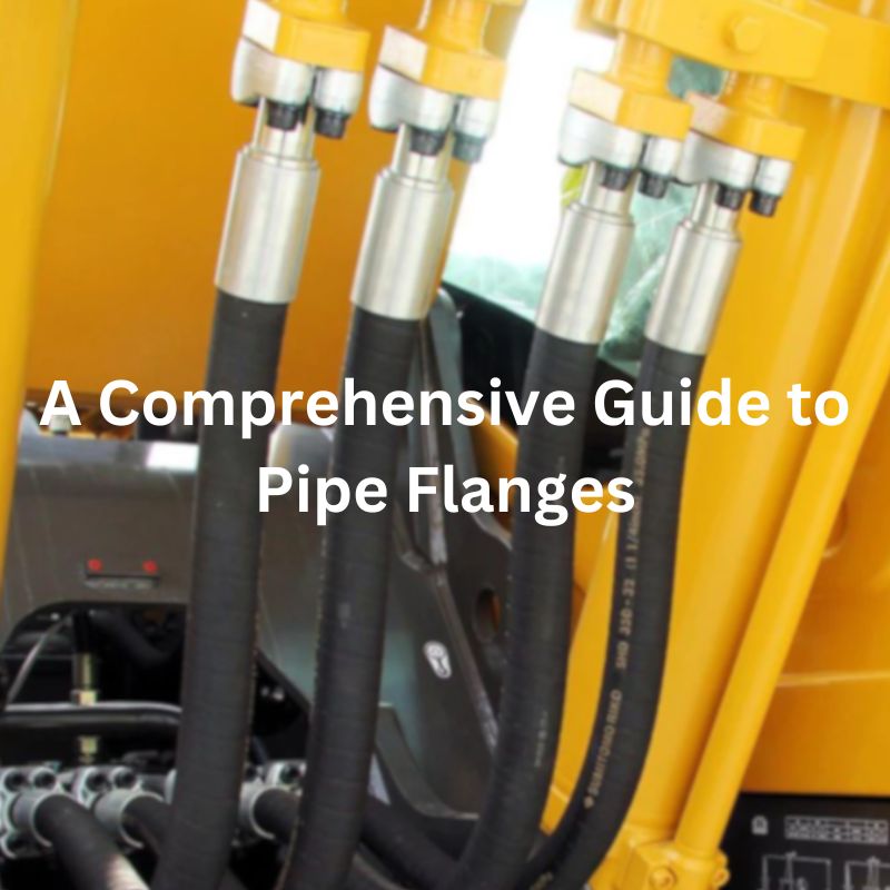
A Comprehensive Guide to Pipe Flanges
Introduction
Piping flanges are critical components that connect pipes, valves, pumps and other equipment used in the construction and maintenance of industrial piping systems. They facilitate the assembly and disassembly of piping structures, making maintenance, inspection, or overhaul during system modifications easier. The purpose of this guide is to provide an in-depth discussion of pipe flanges, giving the reader a comprehensive understanding of the types, materials, specifications and applications of pipe flanges.
Understanding Pipe Flanges
At its core, a pipe flange is a mechanical device designed to connect sections of pipe or to join a pipe to a pressure vessel, pump, valve, or any other piece of equipment. Flanges provide flexibility in piping systems, enabling the disassembly for cleaning, inspection, or modification. The fundamental role of pipe flanges extends beyond mere connectivity; they also provide strength and support, ensuring a sealed and secure system capable of withstanding operational pressures and environmental conditions.Key components of a pipe flange assembly include the flanges themselves, gaskets to ensure a tight seal, bolts, and nuts for securing the flange connection.
Types of Pipe Flanges
Weld Neck Flanges
Weld neck flanges are distinguished by their long tapered hub, which provides important stress distribution benefits. These flanges are welded to the pipe, ensuring a strong, tight connection. Ideal for high-pressure and high-temperature applications, weld neck flanges are commonly used in demanding environments such as the petrochemical industry.
Advantages
Stress Distribution: The tapered hub provides excellent stress distribution, significantly reducing the risk of stress-induced failures.
Durability: These flanges are highly resistant to dents, deformations, and leaks, making them suitable for long-term use in demanding environments.
High-Pressure Resistance: Ideal for applications involving high pressure, where the integrity of the connection is critical.
Disadvantages
Cost: The complexity of the design and the need for precision welding make weld neck flanges more expensive than other types.
Installation: Requires skilled labor and careful preparation to install correctly, adding to the overall project timeline and cost.

Slip-On Flanges
Slip-on flanges are designed to slip over the end of a pipe and then welded in place, both at the inside and outside of the flange. This type is simpler and less costly than weld neck flanges, making it suitable for low-pressure applications.
Advantages
Ease of Alignment: The ability to slide the flange over the pipe before welding allows for easier alignment, which is particularly beneficial in complex piping systems or in tight spaces.
Cost-Effectiveness: Lower material costs and reduced labor for installation make slip-on flanges an economical choice for many projects.
Versatility: Suitable for various applications, particularly where the operational pressures and temperatures are within moderate ranges.
Disadvantages
Pressure Limitations: Slip-on flanges are less robust under high pressure compared to weld neck flanges, making them unsuitable for high-pressure applications.
Potential for Leakage: The design of slip-on flanges, which involves welding both inside and outside the flange, can be more prone to leakage if not properly welded, especially in systems subject to fluctuating pressure or temperature.
Blind Flanges
Blind flanges are indispensable in the world of piping, serving a critical function by sealing the end of pipes, pressure vessels, or valve openings. They are essentially ‘blank’ flanges and contain no center hole, making them ideal for terminating piping systems or isolating sections of a pipeline for maintenance, testing, or repair. The versatility and robustness of blind flanges allow them to be utilized across various industries, including oil and gas, petrochemical, and water treatment facilities.
The design of a blind flange is straightforward yet highly effective. It is mounted to the end of a pipe, a valve opening, or at any juncture where a blockage is required. Depending on the application, it can be bolted into place, allowing for the possibility of future system modifications or expansions.
Advantages
Versatility: Can be used in various applications, including high-pressure scenarios.
Safety: Provides a secure method to seal off sections of a pipeline, ensuring safe maintenance and inspection activities.
Future Expansions: Facilitates the expansion of existing piping systems by allowing sections to be sealed off temporarily.
Disadvantages
Limited Accessibility: Once installed, blind flanges restrict access to the system, making them less suitable for systems requiring frequent access or modification.
Threaded Flanges

Threaded flanges offer a unique solution in environments where welding is impractical or hazardous. These flanges are screwed directly onto the pipe without the need for welding, making them ideal for low-pressure applications or in systems where explosive gases are present, and welding could pose a significant risk.
Threaded flanges are designed with threads inside the flange bore which match the external threads on the pipe. This design allows for easy installation and removal, making them perfect for temporary connections or in places where welding is not an option.
Advantages
No Welding Required: Eliminates the need for hot work permits in hazardous areas, reducing installation time and cost.
Easy Installation and Removal: Can be installed without specialized labor, making them ideal for temporary setups or emergency repairs.
Disadvantages
Pressure and Temperature Limitations: Not suitable for high-pressure or high-temperature applications due to the potential for leaks.
Socket Weld Flanges
Socket weld flanges are designed for use in smaller-diameter high-pressure applications. Their design incorporates a socket into which the pipe fits. The pipe is then welded to the flange both around the outer diameter and inside the socket, creating a smooth flow path that minimizes turbulence and erosion.
The design of socket weld flanges is aimed at enhancing the strength of the connection and improving the flow characteristics within the pipe. The internal weld provides a smooth bore with the added strength of a fillet weld around the outside of the flange. This design is particularly advantageous in high-pressure applications where flow integrity and leak prevention are critical.
Advantages
Strong Connection: Provides a robust and high-integrity joint suitable for high-pressure applications.
Smooth Fluid Flow: The internal welding creates a smooth bore that minimizes turbulence and erosion.
Disadvantages
Alignment Challenges: Precise alignment is required before welding to ensure a proper fit and seal.
Potential for Stress: The welding process can introduce stresses if not performed correctly, potentially affecting the integrity of the connection.
Lap Joint Flanges
Lap joint flanges are a preferred choice in piping systems that require frequent disassembly for inspection, cleaning, or maintenance. These flanges work in tandem with stub ends, which are welded to the pipe. The flange itself does not come into direct contact with the fluid in the pipe, which allows for the use of less expensive materials for the flange than the stub end.
The unique design feature of a lap joint flange is its ability to rotate freely around the pipe. This is particularly useful in applications where bolt hole alignment is difficult, as it allows for easy alignment of the bolt holes after the stub end has been welded to the pipe. The stub end also provides a smooth and consistent face for the gasket to seal against, enhancing the integrity of the joint.
Advantages
Flexibility in Maintenance: The ability to freely rotate makes maintenance and inspection tasks simpler and more efficient.
Cost-Effectiveness: Allows for the use of less expensive materials for the flange in corrosive applications, as the flange does not come into contact with the process fluid.
Disadvantages
Requirement for Stub Ends: The need for a stub end can add to the overall cost of the piping system, both in terms of materials and installation.
Materials and Specifications
The selection of materials and adherence to specifications are critical factors in the manufacturing and application of pipe flanges. Flanges are made from a variety of materials, each chosen for its specific properties and suitability for different environments and pressures. The manufacturing and dimensional standards for pipe flanges, governed by internationally recognized organizations, ensure consistency, quality, and safety across all industries.
Materials Used in Pipe Flange Manufacturing
Carbon Steel: Widely used due to its strength and durability. Carbon steel flanges are suitable for high-pressure and temperature applications but are susceptible to corrosion.
Stainless Steel: Known for its resistance to corrosion and oxidation, stainless steel is ideal for use in corrosive environments. It can withstand a wide range of temperatures, making it suitable for various applications.
Alloy Steel: Alloy steel flanges are used in applications requiring higher strength and corrosion resistance. Alloys like chrome-molybdenum steel are common in high-temperature and pressure environments.
Aluminum: Offers excellent corrosion resistance and is lighter than steel. Aluminum flanges are commonly used in the chemical industry and in applications where weight is a concern.
Nickel Alloys: Nickel alloy flanges are ideal for severe environments exposed to high temperatures, corrosive chemicals, and high pressures. They are often used in the petrochemical and nuclear industries.
Standards and Specifications
The manufacturing and dimensional standards for pipe flanges ensure uniformity and compatibility across global industries. Some of the key standards include:
ANSI/ASME B16.5: Governs the dimensions, tolerances, and materials for flanges up to 24 inches in diameter in various pressure classes.
ASME B16.47: Covers larger flanges in sizes ranging from 26 inches to 60 inches, specifying requirements for Series A (MSS SP-44) and Series B (API 605) flanges.
ISO Standards: International standards that provide specifications for flanges used in various industries worldwide, ensuring global interoperability.
DIN Standards: Widely used in Europe, DIN standards specify flange dimensions and materials for a wide range of applications.
Installation and Maintenance
The proper installation and maintenance of pipe flanges are critical to ensuring a leak-free piping system that operates efficiently and safely over its intended lifespan. This chapter provides a general guide to the installation process, routine maintenance practices, and troubleshooting common issues like misalignment and gasket failure.

Installation Guide
Preparation:
Inspect the flange, gasket, and mating surface for any damage or irregularities.
Ensure the compatibility of the flange, gasket, and bolts/nuts in terms of size, pressure rating, and material.
Alignment:
Align the flange faces parallel to each other with the pipe or equipment nozzle to ensure an even seal across the gasket surface.
Gasket Placement:
Place the gasket evenly between the flanges. Ensure that the gasket type is suitable for the fluid, temperature, and pressure of the system.
Bolting:
Insert bolts and hand-tighten nuts to ensure the flange and gasket are correctly positioned.
Use a calibrated torque wrench to tighten the bolts in a cross-pattern sequence to the specified torque. This ensures even distribution of pressure on the gasket.
Final Inspection:
Inspect the assembly for alignment and uniform gasket compression.
Check for any gaps or misalignment that could indicate improper installation.
Routine Maintenance Tips
Regular Inspections:
Conduct visual inspections for signs of leakage, corrosion, or damage to the flange, bolts, and gasket.
Use ultrasonic or other non-destructive testing methods to detect hidden flaws or leaks.
Gasket Replacement:
Replace gaskets during maintenance shutdowns or if there is evidence of compression set or damage.
Bolt Tightening:
Periodically check and retorque bolts, especially after the system has undergone temperature or pressure cycles that could cause loosening.
Troubleshooting Common Issues
Misalignment:
Misalignment can cause uneven pressure on the gasket and lead to leaks. Realign the flanges using suitable tools and techniques, ensuring parallel alignment.
Gasket Failure:
Gasket failure is often due to incorrect selection, over-tightening, or chemical degradation. Inspect the failed gasket to determine the cause and replace it with a suitable type.
Bolt Stress:
Uneven bolt tightening can lead to leaks. Ensure all bolts are tightened uniformly to the manufacturer’s recommended torque settings.
Choosing the Right Pipe Flange for Your Project
Factors to Consider
Size and Pressure Rating:
The flange size must match the diameter of the pipe to which it will be connected. The pressure rating, denoted by classes ranging from 150 to 2500 in most standards, should align with the maximum pressure the system will encounter.
Material:
Material selection is based on the system’s exposure to corrosive substances, temperature ranges, and the type of fluid being transported. Common materials include carbon steel for general applications, stainless steel for corrosion resistance, and alloy steel for high temperature and pressure conditions.
Flange Type:
The choice of flange type (weld neck, slip-on, blind, threaded, lap joint, socket weld) depends on the specific application, including the need for strength, ease of installation, and maintenance requirements. For example, weld neck flanges are preferred in high-pressure applications, while slip-on flanges might be chosen for lower pressure environments.
Standards and Specifications:
Ensure the flange meets international standards (such as ANSI, ASME, ISO, or DIN) relevant to your industry and application. Compliance with these standards guarantees compatibility and safety.
Operational Environment:
Consider the environmental conditions the flange will be exposed to, including temperature extremes, potential corrosive elements, and physical wear. This consideration is crucial for selecting materials and types that will withstand these conditions.
Cost:
While not a technical specification, the cost is a practical consideration. The goal is to select a flange that meets all technical requirements without unnecessary expenditure, balancing initial costs with long-term operational expenses.
Conclusion
Understanding piping flanges is fundamental to designing, installing and maintaining an effective piping system. In this guide, we explore all aspects of piping flanges, including their types, materials, specifications, installation, maintenance methods, and considerations needed to select the right flange for a project. Each section has been carefully designed to provide field professionals with the knowledge they need.
If you still have doubts about pipe flanges, welcome to contact Topa, we will answer you as soon as possible!


