
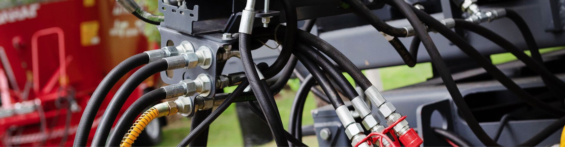
Hydraulic fittings are crucial components in hydraulic systems, allowing the connection of tubes, pipes, and hoses in a secure and efficient manner. These fittings facilitate the flow of fluids and are designed to withstand high pressures and temperatures inherent in hydraulic applications. Choosing the right type of fitting is paramount for system efficiency, safety, and reliability. The selection between flared and flareless fittings, for example, depends on specific system requirements and operational conditions.
Choosing between flared and flareless fittings depends on several factors specific to your application, including system pressure, vibration and dynamic loads, space constraints, and maintenance requirements. Flared fittings utilize a metal-to-metal seal and are ideal for high-pressure applications that require a solid seal. Flare fittings are preferred when tubing can be prepared for flaring and a durable, leak-proof connection is required. Flareless fittings, on the other hand, are better suited for fittings that cannot be prepared for flaring or for use in environments with high vibration or thermal cycling. They are easier to install, especially in confined spaces, and do not require much specialized tooling, giving them an advantage in terms of quick assembly and maintenance. Consider the specific needs and constraints of your system to determine the type of fitting that will provide the best reliability and performance.
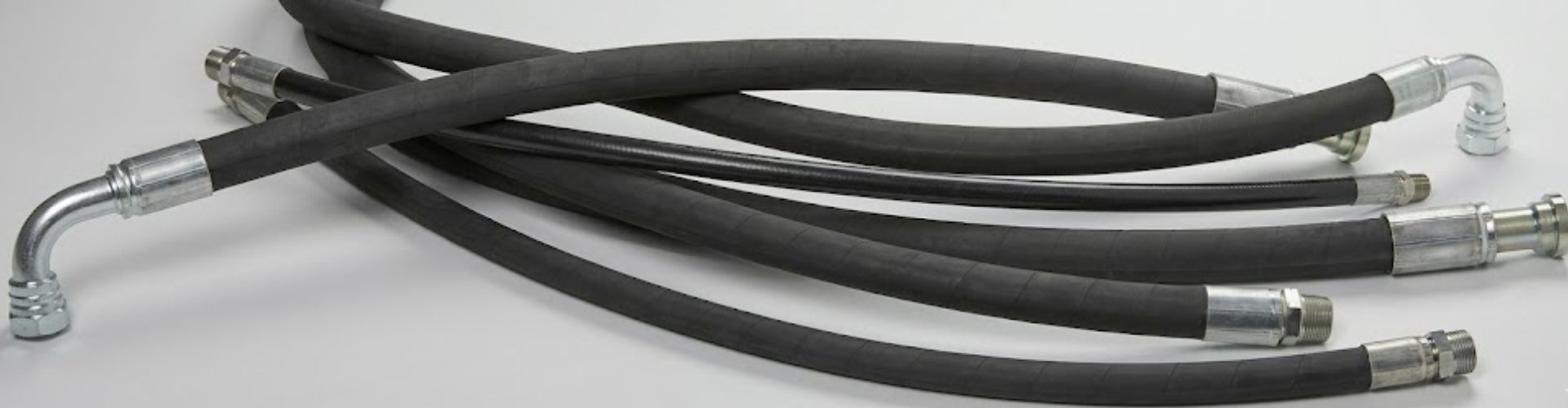
Flared fittings are essential components in various hydraulic and pneumatic systems, recognized for their distinctive conical shape that ensures a tight, leak-proof connection. These fittings are especially valued in high-pressure environments due to their mechanical lock between the flared end of the tubing and the fitting body.
The design of flared fittings involves a flared end of the tubing, which is achieved by using a flaring tool to expand the tube’s end into a cone shape. This flared end then mates with a corresponding tapered surface on the fitting, and a nut secures the connection, compressing the flare against the fitting to create a seal. This design is particularly effective in preventing leaks, making it suitable for critical applications in aerospace, automotive braking systems, and refrigeration lines.

Aerospace
In the aerospace industry, the safety and reliability requirements are exceptionally high. Flared fittings are used in fuel, hydraulic, and pneumatic systems on aircraft and spacecraft. Their ability to maintain a leak-proof seal under extreme pressure and temperature variations is crucial for the safety and functionality of aerospace equipment.
Automotive Systems
Flared fittings are integral to automotive braking systems, fuel lines, and hydraulic steering systems. The automotive industry values these fittings for their durability and leak-proof performance, which are essential for vehicle safety and efficiency. Their use in braking systems is particularly critical, where failure can have dire consequences.
Refrigeration
The refrigeration industry relies on flared fittings to ensure secure connections within cooling systems. These systems require precise control over the flow and containment of refrigerants. Flared fittings provide the necessary seal and reliability to maintain system efficiency and prevent leaks, which can be costly and harmful to the environment.
Ease of Assembly and Disassembly: Flared fittings can be easily assembled and disassembled without special tools, making them ideal for field repairs and maintenance.
Robustness Against Leaks: The mechanical seal created by the flared tubing provides a high level of leak resistance, crucial in high-pressure applications.
Suitability for Thin-Walled Tubing: The flaring process strengthens the end of the tube, allowing for the use of thin-walled tubing without compromising the connection’s integrity.
The most frequently used flare fitting in hydraulic systems is the 37-degree flare fitting, also known as the JIC (Joint Industry Council) fitting. This fitting is widely adopted across various industries due to its reliability and the metal-to-metal seal it provides, making it suitable for high-pressure applications.
Often referred to as compression or bite fittings, flareless fittings are unique in that they secure hydraulic lines without flaring. The centerpiece of the flareless fitting design is the ferrule or bite ring. This component plays a vital role as it clamps down on the tubing as the fitting is assembled. This action creates a strong, leak-proof seal that is critical to the integrity of the hydraulic system.
Oil and Gas Industry
In the oil and gas industry, flareless fittings are used in both upstream exploration and production activities as well as downstream processing and distribution systems. Flareless fittings are able to withstand the high pressure environments typical of oil and gas applications.
Mining
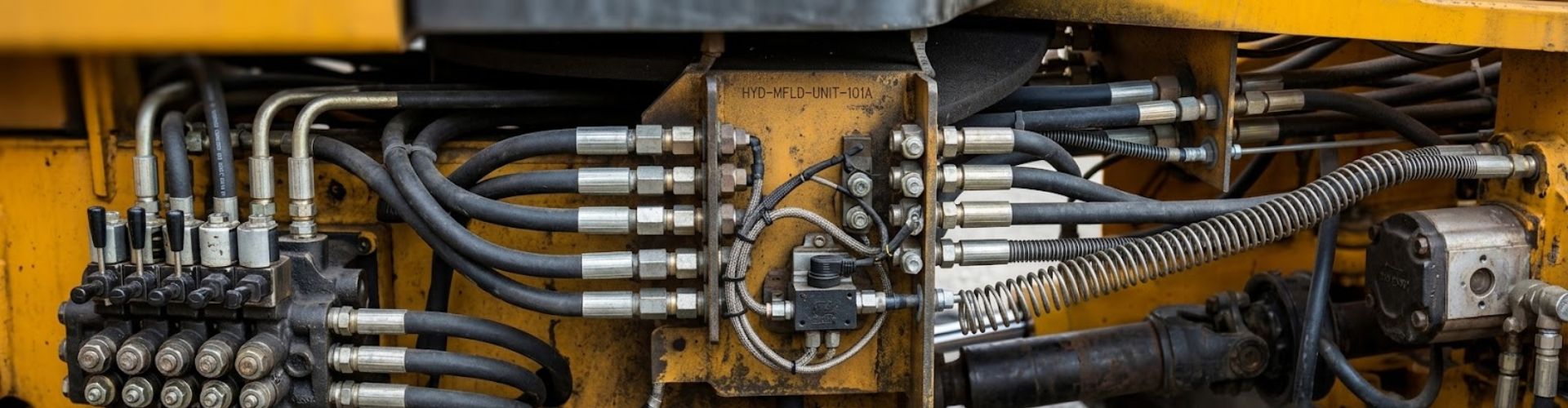
The mining industry relies on heavy machinery and hydraulics to operate under extreme conditions of high pressure, dust and vibration. Flareless couplings are used in drilling equipment, conveyor systems and hydraulic shovels for their ruggedness and ease of maintenance.
Heavy Machinery
Construction, agricultural and forestry equipment use hydraulics for a wide range of functions. Flareless couplings are reliable under dynamic loads and can withstand the vibrations and shocks common in heavy machinery operations.
Ease of Installation: Flareless fittings can be installed in confined spaces, making them ideal for complex hydraulic systems where space is limited.
Reliability in Vibration-Prone Environments: The mechanical grip of the ferrule ensures a secure seal that is less likely to loosen under vibration, making flareless fittings suitable for mobile hydraulics and machinery that experiences significant movement.
Reduced Risk of Leaks: The tight seal formed by the compression of the ferrule against the tube greatly reduces the likelihood of leaks, essential for maintaining system efficiency and preventing environmental contamination.
When selecting the appropriate type of fitting for a hydraulic system, it’s essential to consider several key factors that influence performance, reliability, and maintenance needs. Here’s a detailed look at these considerations:

High-Pressure Systems: Flared fittings are typically favored for high-pressure applications due to their robust seal and durability. The design of a flared fitting, which includes a flared tube end that mates with a tapered fitting, provides a reliable seal capable of withstanding high pressures. This makes them ideal for use in applications such as aerospace, high-performance automotive systems, and industrial machinery.
Temperature Considerations: Both flared and flareless fittings can accommodate a range of temperatures, but the choice may depend on the specific temperature extremes the system will encounter. Material compatibility and thermal expansion factors should also be taken into account.
Vibration-Prone Environments: Flareless fittings are often preferred in environments subject to significant vibration or dynamic loads. The mechanical grip of the ferrule in a flareless fitting ensures a secure connection even under fluctuating conditions, reducing the risk of leakage or disconnection. Mobile equipment, heavy machinery, and certain industrial applications can benefit from the reliability of flareless fittings in these contexts.
Ease of Assembly: Flareless fittings offer a distinct advantage in ease of assembly, especially in tight or confined spaces where using tools to create a flared end is impractical. This feature makes them suitable for field repairs or in situations where quick assembly and disassembly are required.
Maintenance Needs: Considering the maintenance requirements of the system is also crucial. Flareless fittings can be easier to maintain due to their simpler assembly and disassembly process. This can lead to reduced downtime and lower maintenance costs over the system’s lifespan.
Space Constraints: In systems where space is at a premium, the compact design of flareless fittings may offer an advantage.
Tooling and Equipment Availability: The need for specialized tooling for flaring may influence the decision, especially in field applications where such tools might not be readily available.
Cost Implications: The cost of fittings and the necessary installation tools can also be a factor, with flareless fittings potentially offering savings in scenarios requiring less specialized equipment.
The installation of flared fittings is a critical process in hydraulic and pneumatic systems that requires precision and attention to detail. Here’s a detailed expansion on each step of the installation process:
Measure Accurately: Before cutting, accurately measure the tubing length required for your application, considering the entire route the tubing must take, including allowances for bends and fittings.
Cutting the Tubing: Use a sharp, tube-specific cutter to ensure a clean, straight cut. Avoid using saws or tools that might crush or deform the tubing.
Deburring: After cutting, remove any burrs or sharp edges from both the inside and outside of the tubing end using a deburring tool. This step is crucial to prevent damage to the sealing surfaces and ensure a smooth surface for the flare.
Selecting the Correct Die: Choose the correct die for the tubing diameter. The die’s size should match the outer diameter of the tubing.
Inserting the Tubing into the Flaring Tool: Insert the tubing into the flaring tool’s clamp section, making sure the tubing end protrudes slightly above the die according to the manufacturer’s specifications.
Creating the Flare: Tighten the flaring tool’s press against the tubing end to form a 45-degree flare. The flare should be smooth and free of cracks or splits.
Inspecting the Flare: Before assembly, inspect the flare for any imperfections. A perfect flare is crucial for a leak-proof seal.
Aligning the Tubing with the Fitting: Insert the flared end of the tubing into the fitting until it seats against the fitting’s conical surface.
Thread the Nut: Place the nut over the tubing and thread it onto the fitting by hand to ensure it is not cross-threaded.
Tightening: Using two wrenches, one to hold the fitting and the other to tighten the nut, secure the connection. Follow the manufacturer’s recommended torque specifications to avoid over-tightening, which could crack the flare or under-tightening, which might result in leaks.
Leak Testing: Once installed, it is crucial to test the system under pressure to ensure there are no leaks at the flared connections.
Regular Checks: Periodically check the fittings for signs of leaks, especially after the system has been in use, as vibrations and temperature changes can affect the integrity of the connection.
The installation of flareless fittings, while straightforward, demands precision to achieve a reliable connection. Here’s a more detailed look at each step:
Preparation: Before inserting the tube into the fitting, ensure the tube end is clean, free of burrs, and cut perpendicular to its length. This preparation is crucial for a proper seal and to prevent damage to the fitting components.
Insertion: Carefully insert the tube into the fitting until it reaches the stop point. This stop point is typically a shoulder within the fitting body designed to ensure the correct insertion depth of the tube.
Initial Hand Tightening: Thread the nut onto the fitting by hand to prevent cross-threading. This also helps to ensure that the ferrule is correctly positioned before the final tightening.
Wrench Tightening: Using a wrench, tighten the nut to the manufacturer’s recommended torque. This compresses the ferrule against the tube, creating a metal-to-metal seal. The ferrule effectively “bites” into the tube, which is what secures the connection and ensures its leak-proof nature.
Correct Torque: It’s essential to apply the correct amount of torque; too little may result in a leaky connection, while too much could damage the tube, ferrule, or fitting. Some fittings may require a specific tightening procedure to ensure proper ferrule action.
Visual Inspection: After installation, visually inspect the fitting to ensure it is correctly assembled and that there are no visible gaps between the tube and the fitting.
Leak Testing: Perform a pressure test to confirm the integrity of the connection. Any leaks at this stage would require re-evaluation of the assembly process, possibly disassembly, inspection, and re-tightening or replacement of components.
Record Keeping: Documenting the installation can be helpful for future maintenance or troubleshooting. Note the date of installation, any unique conditions, and the torque applied.
The choice between flared and flareless fittings depends on a thorough assessment of system requirements, including pressure, temperature, and environmental conditions. Understanding the unique advantages and installation techniques of each fitting type allows for informed decision-making, ensuring the hydraulic system’s efficiency, safety, and reliability. By adhering to best practices in selection, installation, and maintenance, operators can optimize the performance and lifespan of their hydraulic systems.
A flared fitting uses a conical flare at the end of the tube to create a tight seal when paired with a matching flare nut.
A flareless fitting uses a compression ring and a nut to create a seal without requiring a flare on the tube.
Flared fittings are typically better for high-pressure applications due to their robust seal created by the flared end.
Flared fittings are typically better for high-pressure applications due to their robust seal created by the flared end.
Yes, flareless fittings are easier and quicker to install since they don’t require flaring the tube before installation.
Flareless fittings can sometimes replace flared fittings, but compatibility depends on the application and pressure requirements.
Find out more about Topa Blog and learn more about specialized hydraulic fittings.

Automated page speed optimizations for fast site performance
