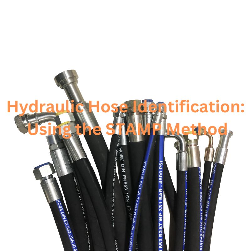
Hydraulic Hose Identification: Using the STAMP Method
Table of Contents
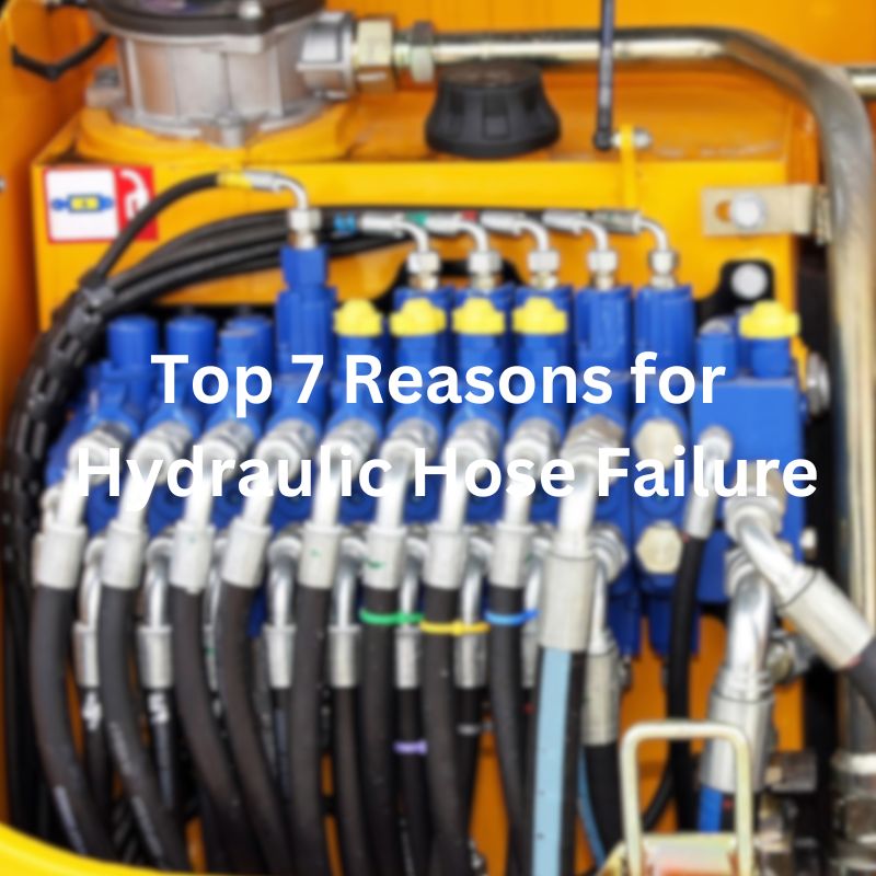
Introduction
Incorrect hose selection can lead to catastrophic failures, costly downtime, and even serious safety hazards. This article will introduce a systematic approach known as the STAMP method, which is the cornerstone of selecting the correct hydraulic hose for any application, ensuring that all critical factors are systematically considered.
The Significance of Proper Hydraulic Hose Identification
When it comes to maintaining and operating hydraulic systems, the importance of correctly identifying hydraulic hoses cannot be overstated. Misidentifying a hydraulic hose might seem like a small oversight, but it can have disastrous consequences. Here’s why proper hose identification is absolutely crucial:
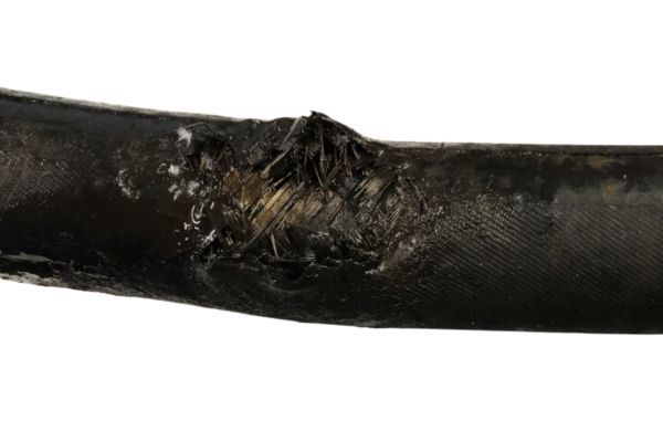
Preventing Equipment Damage: Imagine a scenario where a hydraulic hose that is not suited for high pressure is mistakenly used in a high-pressure application. The hose could burst, leading not only to system downtime but also to potential damage to expensive machinery. By ensuring each hose matches the system’s requirements, you drastically reduce the risk of damaging critical components.
Enhancing Safety: Hydraulic hose failures can be dangerous. In high-pressure applications, a burst hose can fling about violently, posing serious risks to operator safety. Correct hose identification helps prevent these kinds of accidents, ensuring a safer work environment.
Optimizing System Efficiency: A hydraulic system is only as good as its weakest component. Using hoses that perfectly match the specifications of the system helps maintain optimal efficiency. Whether it’s the right material to handle the fluid type, the correct diameter to manage fluid flow, or the appropriate length to fit the system layout, each factor plays a part in system performance.
Understanding the STAMP Method
Navigating the complexities of hydraulic hose selection is made simpler with the STAMP method. This approach breaks down into five crucial elements—Size, Temperature, Application, Material, and Pressure—each accompanied by Ends considerations for fitting types. Here’s how each component plays a critical role in ensuring the right hose selection:
S=Size
When considering the size of a hydraulic hose, it’s essential to focus on both the inner diameter and the length. These dimensions are not arbitrary; they are chosen based on the specific requirements of the hydraulic system they will serve.
Inner Diameter: The diameter must be adequate to accommodate the flow rate of the fluid without causing excessive friction or heat buildup, which can degrade the hose over time. If the diameter is too small, it will restrict flow, resulting in a high velocity that can erode the inner lining of the hose and lead to premature failure. Conversely, a hose that is too large for the system can result in insufficient fluid velocity, leading to inefficiencies such as poor hydraulic response and increased energy consumption to move the fluid.
Length: The length of the hose also plays a crucial role. It should be long enough to connect the necessary components without stressing the hose, which can occur if the hose is stretched to meet connection points. However, excessive length can lead to complications such as pressure drops, potential kinks, and greater overall system complexity. Additionally, longer hoses contain more fluid and therefore add to the hydraulic fluid’s compressibility factor, which can affect the performance and responsiveness of the system.

T=Temperature
Hoses are exposed to various temperatures based on the fluid they carry and their environmental conditions.
Operating Temperature Range: Each hose is designed to operate within a specific temperature range. This range includes the minimum and maximum temperatures the hose material can withstand without degradation. If a hose is subjected to temperatures outside this range, the material may become too soft or too brittle, leading to structural failures such as cracks, leaks, or bursts.
Material Selection: The material composition of the hose is critical in determining its temperature tolerance. Common materials include synthetic rubbers like Nitrile and Neoprene, which offer good resistance to oil-based hydraulic fluids and can handle a broad range of temperatures. For higher temperature applications, hoses made from materials like EPDM (ethylene propylene diene monomer) or Silicone might be necessary due to their ability to withstand higher heat without degrading.
Heat-induced Expansion and Contraction: Thermal expansion and contraction can affect hose integrity and fitting security. Materials that expand significantly with temperature increases might compromise the tightness of the connection points, potentially leading to leaks. Similarly, contraction in cold environments can make the hoses stiff and brittle, increasing the risk of cracking.
Environmental Considerations: External environmental conditions also play a role in hose selection. For instance, hoses used outdoors in regions with extreme temperature variations need to be durable enough to handle these changes without failing. Hoses used near hot machinery or in direct sunlight must also be resistant to ambient heat sources.
Application-specific Requirements: Certain applications may require hoses that can handle extreme bursts of heat, such as those found near engines or exhaust systems. In these cases, specialized high-temperature hoses with reinforced heat resistance need to be used to ensure safety and functionality.
A=Applications
Selecting the right hydraulic hose for a specific application involves a detailed understanding of the hydraulic system’s requirements and the operational environment. Here’s how to ensure the hose you choose meets your applications:
System Design Requirements: Each hydraulic system is designed for specific tasks and operational parameters. The chosen hose must accommodate the system’s pressure ratings, flow rates, and fluid type. For instance, a system designed for high-pressure operations such as hydraulic jacks or industrial machinery will require hoses with strong reinforcement layers that can handle the pressure without bursting.
Environmental Conditions: The operating environment plays a critical role in hose selection. Hoses exposed to harsh chemicals, and abrasive materials need materials specifically designed to withstand these conditions. For example, hoses used in a marine environment should have excellent resistance to water, salt, and possibly UV light, while hoses used in mining or construction need to be highly abrasion-resistant.
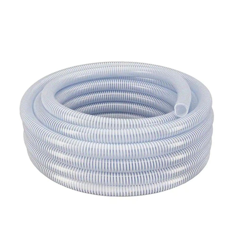
Flexibility and Space Constraints: In many hydraulic systems, especially in complex machinery or compact spaces, the hoses must be flexible enough to fit into tight spaces or around corners without kinking or bending in ways that impede fluid flow. Flexibility is also important to accommodate the movement of machine parts relative to each other.
Rigidity for High-Pressure Operations: While flexibility is important, certain high-pressure applications may require more rigid hoses to ensure stability and durability under pressure. Hoses with multiple reinforcement layers or stiffer materials may be needed to prevent expansion under pressure, which can affect the hydraulic system’s efficiency and responsiveness.
Custom Requirements: Some systems may have specific requirements based on their operational needs, such as non-conductive hoses for use in electrical environments or food-grade hoses for applications involving food products. Each of these scenarios demands hoses designed with particular characteristics to safely and efficiently handle the job.
M=Material
Choosing the correct material for a hydraulic hose is paramount because the hose needs to handle the specific chemical properties of the fluid it transports. Chemical incompatibility can lead to severe issues, such as degradation of the hose material, which compromises the integrity and safety of the entire hydraulic system. Here’s how to ensure the hose material is appropriate for the application:
Understanding Fluid Types: Hydraulic systems can use a variety of fluids, including mineral oils, synthetic oils, glycol-water-based fluids, and more. Each type of fluid has specific chemical properties that can affect the inner lining of the hose. For instance, synthetic oils can degrade certain types of rubber that are stable with mineral oils.
Hose Material Selection: The most common materials for hydraulic hose liners are synthetic rubbers like Nitrile, which is resistant to oil-based hydraulic fluids, and Polytetrafluoroethylene (PTFE), which is compatible with more aggressive chemicals like acids and alkalis.
- Nitrile Rubber (NBR): Good for oils and fuels because of its resistance to swelling. It performs well with most mineral and oil-based hydraulic fluids but is not suitable for phosphates-ester-based fluids.
- Polytetrafluoroethylene (PTFE): Known for its high chemical resistance, it can handle nearly all industrial chemicals, making it ideal for applications involving corrosive fluids.
- Chloroprene (Neoprene): Offers good weather resistance and handles moderate acids and other chemicals. It is often used in refrigerants in air conditioning systems.
- Ethylene Propylene Diene Monomer (EPDM): Excellent for glycol-based brake fluids and steam applications but not suitable for oil-based fluids.
P=Pressure
The working pressure of a hydraulic hose must match or exceed the maximum operating pressure of the system. It’s essential to consider not just the normal operating pressure but also any transient spikes that can occur during operations. These spikes can result from rapid changes in load or sudden obstructions, like when a backhoe strikes a rock, causing a sharp, short-lived increase in pressure.
Static vs Dynamic Systems
Hydraulic systems can be categorized into static and dynamic:
- Static Systems: These systems use non-moving fluids to transmit force. An example is a hydraulic jack, where pressure applied to a confined liquid is used to lift heavy loads.
- Dynamic Systems: In these systems, fluid is in motion, driven by pumps to transfer energy to various components. Backhoes and other heavy machinery typically operate on dynamic hydraulic systems.
- Operating Pressure: Each hydraulic hose is rated for a specific maximum operating pressure. It’s essential that the hose’s rating meets or exceeds the highest pressure expected in the hydraulic system under normal conditions. Using a hose with a pressure rating lower than the system’s requirement can lead to hose rupture, leakage, or complete failure.
Pressure Spikes
Hydraulic systems can experience transient pressure spikes that exceed the normal operating pressure, often due to sudden changes in load or velocity. These spikes can be significantly higher than the average working pressure and can cause damage if the hose is not designed to handle such stress. Therefore, it’s important to choose a hose that can tolerate these occasional increases. Many hoses are designed to handle pressure spikes up to a certain percentage of their rated capacity without sustaining damage.
Managing Pressure Drop
Pressure drop within hydraulic systems can significantly affect performance and is influenced by several factors:
Friction and Viscosity: As fluid moves through a hose, it experiences friction, particularly if the hose’s inner diameter (ID) is too small, leading to increased resistance and heat. The viscosity of the fluid also plays a role, with thicker fluids slowing down the flow and increasing pressure drop.
Ambient and Fluid Temperatures: Temperature affects fluid viscosity. In colder environments, fluids thicken, increasing pressure drop, whereas they thin out in warmer conditions, potentially reducing pressure drop but also leading to other risks like seal damage.
Hose Length and Diameter: Longer hoses increase the surface area where friction can occur, elevating pressure drop. Similarly, a hose with a small diameter can restrict flow, increasing velocity and pressure drop. Conversely, a larger diameter hose reduces pressure drop, allowing for smoother fluid flow.
Couplings and Adapters: Changes in direction or reductions in hose bore size at couplings and adapters can create turbulence or restrictions, increasing pressure drop.
Safety Factor: Typically, hydraulic hoses are selected with a safety factor in mind. This factor generally ranges from 4:1 to 8:1, meaning the hose is capable of withstanding four to eight times its rated working pressure before failing. This safety factor accounts for variations in pressure, weaknesses in the hose material over time, and unforeseen spikes in pressure.
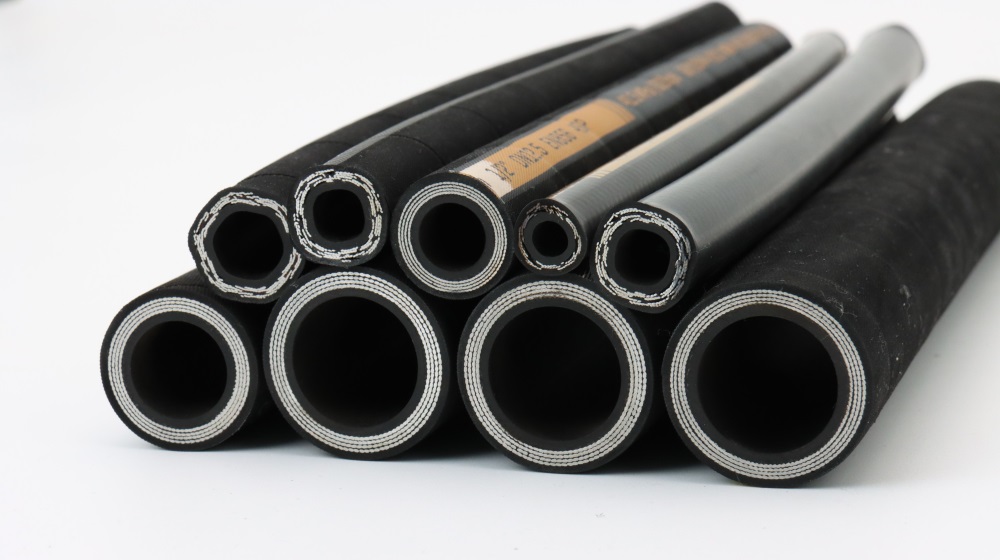
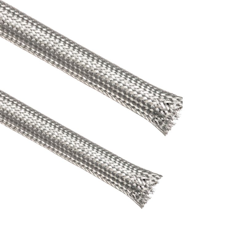
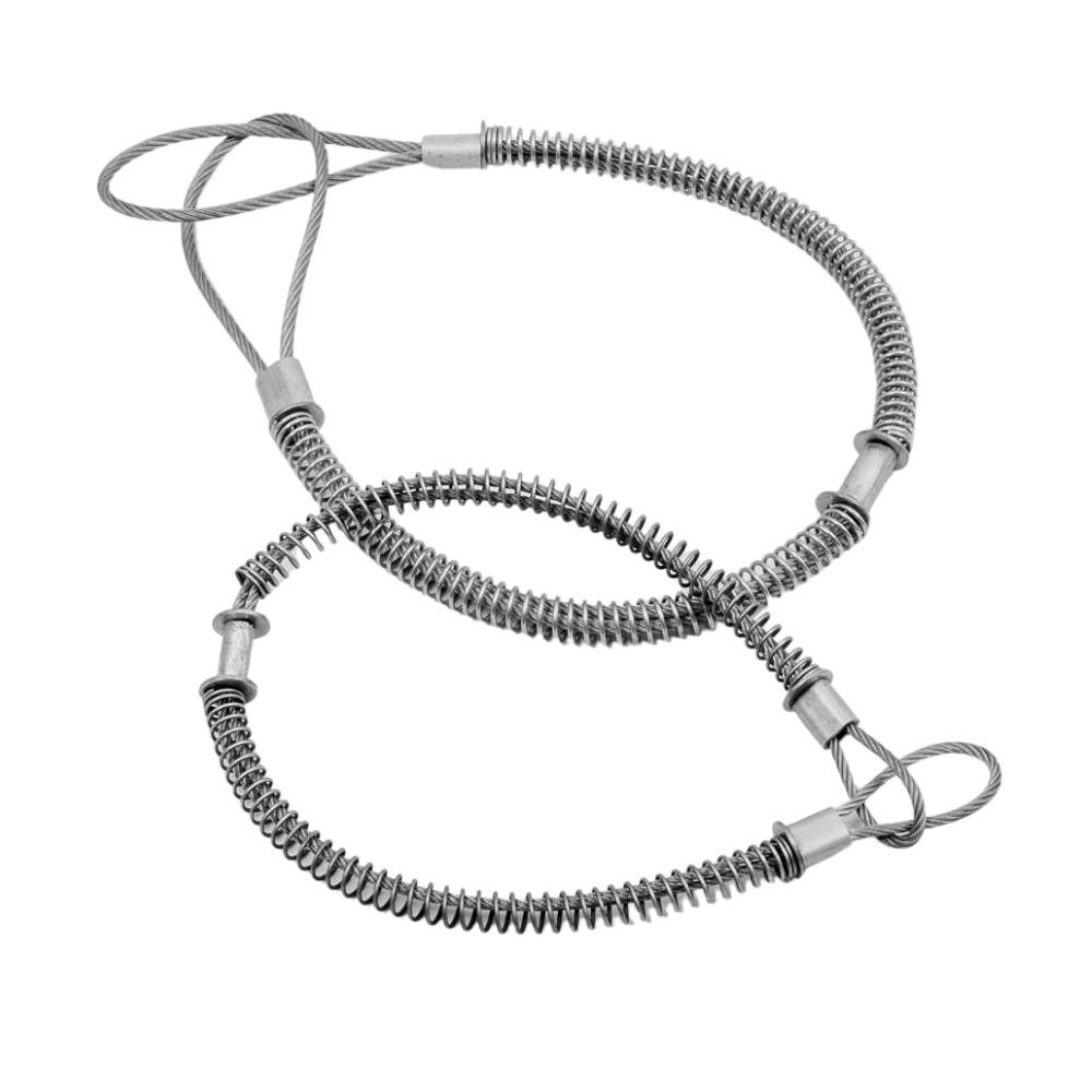
Reinforcement Layers: Hoses are reinforced with layers of wire braid or spiral-wound wire to strengthen them against high pressure. The number of layers and the strength of the reinforcement will determine the maximum pressure the hose can withstand. High-pressure applications typically require hoses with multiple layers of reinforcement.
Practical Guide to Applying the STAMP Method

The STAMP method provides a structured approach to selecting the right hydraulic hose for specific applications. Here’s a step-by-step guide to effectively apply this method, ensuring that your hydraulic system operates safely and efficiently:
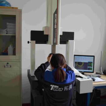
Measure the Hose Size Accurately
Proper hose size is crucial for system efficiency and preventing leaks. Use precise measuring tools like calipers to determine the inner diameter (ID) and outer diameter (OD) of the hose. This measurement ensures that the hose can accommodate the flow rate without excessive pressure loss or velocity that might lead to hose wear or failure.
Consult Material Compatibility Charts
Different hydraulic fluids require hoses made from materials that can resist the chemical properties of the fluid. Consult material compatibility charts to ensure the hose material is suitable for the type of fluid in your system. These charts are typically provided by hose manufacturers and detail how different materials react to various hydraulic fluids, including oils, solvents, and acids.
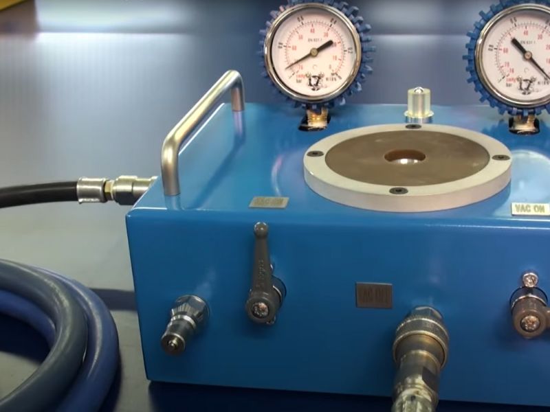
Check Temperature and Pressure Ratings
Verify that the hose can withstand the maximum operating temperature and pressure of the hydraulic system. Hoses are rated for specific temperature ranges and maximum pressures. Exceeding these ratings can lead to hose degradation, loss of integrity, and potential failure. Consider both the fluid temperature and the ambient temperature in which the hose will operate.
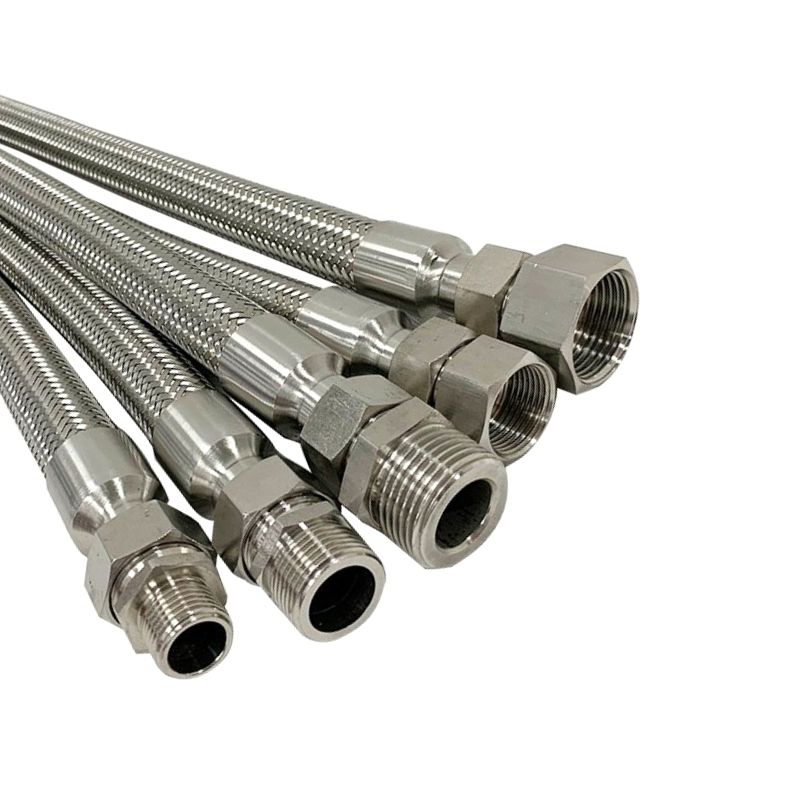
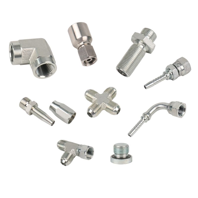
Select Appropriate Fittings
Choosing the right fittings is just as important as selecting the hose. Ensure the fittings you choose match the hose in terms of size, material, and design. This compatibility is crucial to create a secure, leak-free connection. The fittings should also be suitable for the system’s pressure and not introduce any weak points.
Common Mistakes in Hydraulic Hose Identification
In the selection and maintenance of hydraulic hoses, certain pitfalls can lead to system inefficiencies, premature hose failure, or even dangerous blowouts. Recognizing these common mistakes can significantly improve the reliability and safety of hydraulic systems. Here’s an overview of typical errors and how to avoid them:
Mismatching Material Compatibility
One of the most critical mistakes in hydraulic hose selection is the failure to match hose materials with the chemical properties of the fluid being transported. This oversight can lead to:
Chemical Degradation: Certain hose materials may degrade when exposed to specific chemicals in hydraulic fluids, such as oils, solvents, or acids.
Corrosion: Incompatible materials can corrode when exposed to certain fluids, leading to weakened hose structure and eventual failure.
Prevention Tip: Always consult material compatibility charts provided by manufacturers to ensure that the hose material is suitable for the type of fluid used in your system.
Underestimating Pressure Spikes
Another frequent error is neglecting to account for pressure spikes in hydraulic systems. These spikes can occur due to sudden changes in load or blockages and may exceed the normal operating pressure by a significant margin.
Hose Bursts: If a hose is not rated to handle occasional spikes, it may burst under pressure, leading to potential safety hazards and system downtime.
System Stress: Even if the hose does not burst, pressure spikes can stress other components of the hydraulic system, reducing overall life expectancy.
Prevention Tip: Ensure that the chosen hose has a maximum pressure rating that accommodates potential spikes, typically by selecting a hose with a burst pressure rating at least four times higher than the system’s maximum operating pressure.
Ignoring Installation Errors
Improper installation of hydraulic hoses can also lead to issues such as leaks, restricted flow, or hose damage:
Improper Routing: Hoses that are bent too tightly, or routed near sharp edges or high-heat areas, can degrade faster or become damaged.
Inadequate Length: Hoses that are too short may be subject to excessive tension, whereas hoses that are too long can kink or tangle.
Prevention Tip: Follow proper routing practices as specified in installation manuals, and ensure that there is enough hose length to allow for movement without stretching or compressing the hose excessively.
Overlooking Environmental Factors
The environment in which a hydraulic hose operates can significantly affect its durability and performance. Common oversights include:
Temperature Extremes: Failing to consider the ambient temperature range can lead to improper hose selection.
Abrasive Conditions: Exposure to abrasive materials can wear down the hose cover and eventually the reinforcement layers.
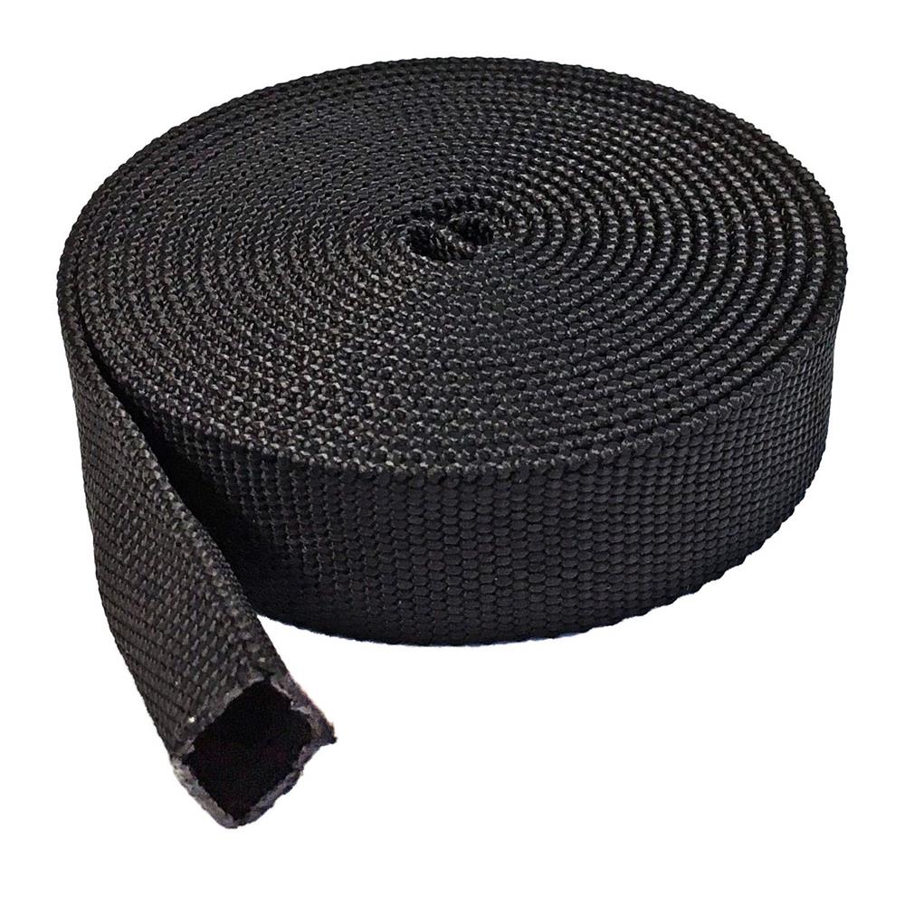
Prevention Tip: Choose hoses with protective covers suitable for the operating environment and consider using additional protective sleeves or guards where necessary.
By following these guidelines, you can improve the reliability, efficiency and safety of your hydraulic system, avoid costly failures and maximize operational efficiency.
FAQ
Consider the STAMP factors: Size, Temperature, Application, Material, and Pressure, to ensure the hose meets the specific requirements of your hydraulic system.
Refer to material compatibility charts to verify that the hose material can resist the chemical properties of the fluid used in your system.
Choose a hose with a burst pressure rating at least four times higher than the maximum operating pressure to handle pressure spikes safely.
Mismatched or improper fittings can introduce weak points, leading to potential leaks and hose failures, so ensure fittings match the hose in terms of size, material, and design.
Avoid mismatches in material compatibility and underestimating pressure requirements. Also, ensure proper installation to prevent physical damage and premature wear.
Consider the operational environment, such as temperature extremes and exposure to abrasive elements, and select hose materials and coverings that can withstand these conditions.


