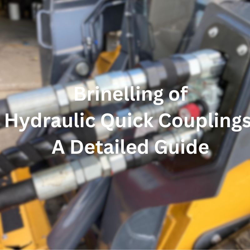
How to Install Hydraulic Quick Coupler banner

How to Install Hydraulic Quick Coupler: Common Mistakes to Avoid

The most significant benefit of correctly installing a hydraulic quick coupler is the prevention of leaks. Leaking hydraulic fluid can lead to environmental hazards, loss of system pressure, and a decrease in overall efficiency. Additionally, leaks often result in expensive repairs and costly downtime. When the coupler is installed properly, it ensures a secure seal, maintaining pressure integrity and ensuring that the hydraulic fluid stays where it needs to be.

Step-by-Step Guide: How to Install Hydraulic Quick Coupler

Installing a hydraulic quick coupler might seem like a straightforward task, but the process requires precision and attention to detail to ensure everything works as it should. Following the right steps helps guarantee a secure, leak-free connection that maximizes the efficiency and safety of your hydraulic system. Below, we’ve broken down the installation process into easy-to-follow steps.

Step 1: Preparing the Hydraulic System for Installation

Before diving into the actual installation, it’s essential to prepare the hydraulic system. First, turn off the power or pressure to the system to avoid accidents. Next, depressurize the hydraulic lines by releasing any built-up pressure, either through valves or a separate release mechanism. This step is crucial to prevent hydraulic fluid from spraying or leaking when you disconnect old couplings or install new ones. Finally, inspect the system for any existing damage or issues that could interfere with the installation process. Make sure all components are in good condition, and if necessary, clean or replace any parts before moving forward.

Step 2: Ensuring Cleanliness – The Importance of Clean Surfaces

One of the most important yet often overlooked aspects of hydraulic system installation is cleanliness. Dirt, debris, or even oil residues on the surfaces of the coupler and connectors can prevent a proper seal, leading to leaks or system malfunctions. Before installation, thoroughly clean the surfaces where the quick coupler will be connected. Use a clean, lint-free cloth or an appropriate cleaning solution to wipe down the components. Additionally, ensure that the hydraulic lines are free from contaminants, as particles can damage seals and O-rings, reducing the lifespan of the coupler.

Step 3: Correctly Aligning the Coupler and Connector

Proper alignment is essential to ensure that the hydraulic quick coupler connects seamlessly. If the coupler and connector are misaligned, it can cause leaks, difficulty in coupling, and excessive wear. When positioning the quick coupler, make sure that the male and female components align perfectly, with no angular distortions. The coupling should slide in smoothly without resistance. Take your time to check alignment before securing it in place to avoid problems that could arise later in the installation process.

Step 4: Tightening the Quick Coupler – Torque Specifications to Follow

Once the coupler is aligned, it’s time to tighten it. However, it’s important to follow the recommended torque specifications for the coupler. Over-tightening can damage the threads or cause excessive pressure on the seals, while under-tightening can lead to leaks. Always refer to the manufacturer’s guidelines for the correct torque value for your specific quick coupler model. You can use a torque wrench to ensure that you apply the correct amount of force. Tighten the coupler in gradual increments rather than all at once to ensure even pressure distribution across the connection.

Install Hydraulic Quick Coupler

Step 5: Final Checks and Pressure Testing the Installation

After the coupler is securely tightened, perform a final visual inspection to ensure that everything looks correct. Double-check for any visible gaps, misalignments, or signs of wear on the seals. Once you’re satisfied with the installation, it’s time for pressure testing. Apply pressure to the hydraulic system and observe the coupler and surrounding area for leaks. If you notice any fluid escaping, depressurize the system, correct the issue, and re-test until the installation is leak-free. Pressure testing is a crucial step to ensure the system functions correctly under operating conditions and that no issues remain before use.

Common Mistakes to Avoid During Installation

Even with the best intentions, mistakes during hydraulic quick coupler installation can lead to inefficiencies, costly repairs, and even safety hazards. Being aware of common errors and how to avoid them can help ensure that your installation process goes smoothly, and that your hydraulic system functions optimally. Below are some of the most frequent mistakes made during installation and tips on how to avoid them.

Mistake 1: Using Incorrect Coupler Size or Type

One of the most common and critical mistakes is choosing the wrong size or type of hydraulic quick coupler. Using a coupler that’s too small or too large for the system can lead to poor connections, excessive pressure loss, or even failure. Additionally, different types of couplers (e.g., ISO, BSP, NPT) are designed for specific systems and applications. Always verify the required coupler specifications—such as size, thread type, and pressure rating—before purchasing. Refer to system manuals or consult with experts to ensure compatibility with the hydraulic connectors and hoses in your system.

Mistake 2: Not Ensuring Proper Alignment of Components

Misalignment during installation can lead to significant issues like leaking, excessive wear, and difficulty in coupling. If the coupler and connector aren’t aligned correctly, the connection might not form properly, causing stress on the parts and reducing their effectiveness. This mistake often occurs when trying to rush the installation. Be patient and double-check that both the male and female parts of the coupler are perfectly aligned. Proper alignment ensures a smooth connection and prevents damage to the seals, threads, and coupler components.

Mistake 3: Over-Tightening or Under-Tightening Connections

Finding the right amount of torque when tightening a hydraulic quick coupler is crucial. Over-tightening can strip threads, damage seals, or even cause cracks in the coupler, while under-tightening can lead to leaks and connection failures. Both issues can compromise the integrity of your hydraulic system. Always refer to the manufacturer’s torque specifications to tighten the coupler to the correct level. Using a torque wrench to ensure accuracy is highly recommended, as it helps you apply even and consistent pressure during installation.

Mistake 4: Ignoring Proper Sealing and O-Ring Installation

The sealing components, such as O-rings and gaskets, play a vital role in ensuring leak-free hydraulic connections. Ignoring proper installation of these parts can result in fluid leakage, pressure loss, or even total system failure. Before installation, inspect the O-rings for signs of damage or wear. Make sure they are properly seated and lubricated according to the manufacturer’s guidelines. Failing to do so can lead to poor sealing and operational inefficiency, as even a small leak can cause significant issues in high-pressure systems.

Mistake 5: Failing to Check for Hydraulic Fluid Compatibility

Another mistake to avoid is failing to check the compatibility of the hydraulic fluid with the coupler material. Hydraulic fluids come in various types, and some can be corrosive to certain metals or seal materials, potentially causing leaks or damage over time. Always ensure that the hydraulic fluid you’re using is compatible with both the coupler and any seals, O-rings, or gaskets in the system. This will not only extend the life of your hydraulic components but will also ensure that the system operates at peak efficiency.

Install Hydraulic Quick Coupler fail

Mistake 6: Not Performing Pressure Testing After Installation

After installing the hydraulic quick coupler, many people skip the crucial step of pressure testing. This oversight can result in undetected leaks or weak connections that could compromise the entire system. Pressure testing is the best way to ensure that the coupler is functioning properly under operational conditions. Always conduct a pressure test after installation to check for leaks or other issues. If any leakage or malfunction is detected, take immediate action to correct the problem before returning the system to full service. This step guarantees the installation is sound and that the system will operate as expected without any surprises.

Troubleshooting Hydraulic Quick Coupler Issues

Even with proper installation, hydraulic quick couplers can sometimes experience issues. Identifying and addressing problems quickly is key to maintaining the performance and safety of your hydraulic system. This section will guide you through troubleshooting common issues like connection failures and poor hydraulic flow, helping you resolve them efficiently.

How to Fix Hydraulic Connection Failures

Hydraulic connection failures can manifest in various ways, including leaks, inability to fully connect, or failure to disconnect properly. Here’s how to troubleshoot and fix these issues:

Check for Misalignment: Often, connection failures are caused by misalignment between the coupler and connector. If the male and female components are not properly aligned, the coupler may not engage or seal properly. Inspect the connection to ensure everything is aligned and that the parts fit snugly together.

Examine for Debris or Contamination: Dirt, rust, or other contaminants can prevent a proper seal or cause damage to the internal parts of the coupler. Clean the connection points thoroughly before reassembling, making sure all components are free from debris. Use lint-free cloths or cleaning tools designed for hydraulic systems to prevent damage.

Inspect Seals and O-Rings: If you notice leaks or difficulty in securing the coupler, check the seals and O-rings. Over time, seals can wear out or become damaged. If you find any visible damage, replace the seals or O-rings with new, compatible parts. Always lubricate O-rings according to the manufacturer’s instructions before installation to ensure proper sealing.

Ensure Correct Coupler Size: If the coupler doesn’t fit properly or fails to engage, it might not be the correct size for your hydraulic system. Verify that the coupler is compatible with the hose or connector in terms of size, thread type, and pressure rating. A mismatched coupler is a common cause of connection failure.

Check for Worn or Damaged Threads: Over-tightening or improper handling during installation can damage the threads on the coupler or connector. Damaged threads can result in leaks or difficulty connecting. If the threads are worn, you may need to replace the affected components.

Troubleshooting Poor Hydraulic Flow After Installation

If you’re experiencing poor hydraulic flow after installing a quick coupler, it’s essential to identify the root cause quickly to prevent system inefficiency or failure. Here are some steps to troubleshoot poor flow:

Verify Proper Coupler Size and Compatibility: If the coupler is too small or incorrectly matched to the system, it can restrict fluid flow. Ensure that the coupler’s flow capacity matches the needs of your hydraulic system. Also, confirm that all couplers, hoses, and fittings are compatible with the fluid flow requirements.

Check for Internal Blockages: A blockage inside the coupler or hoses can restrict the flow of hydraulic fluid. Inspect the hoses, couplers, and connectors for any internal obstructions or buildup, such as dirt, corrosion, or debris. If blockages are found, clean the components thoroughly or replace them if necessary.

Examine for Valve Malfunctions: Some hydraulic quick couplers have built-in valves that help control the flow of hydraulic fluid. If these valves become stuck, damaged, or malfunctioning, they can cause poor flow. Check the valve components for signs of wear or damage, and replace any faulty valves.

Inspect for Leaks in the System: Leaks can reduce the overall pressure and flow in a hydraulic system. Even small leaks in the coupler or hose can result in a noticeable decrease in hydraulic flow. Check all connections, seals, and hoses for leaks, and replace any damaged parts as needed.

Test for Proper Pressure Settings: Low pressure can also lead to poor flow. After installation, check the system’s pressure settings to ensure they are within the recommended range. If the pressure is too low, you may need to adjust the pressure relief valve or check for any issues that could be preventing the system from building adequate pressure.

Ensure Proper Coupler Operation: Finally, ensure that the coupler is functioning properly. Some quick couplers, especially those with automatic shutoff or check valves, may not operate correctly if the internal mechanism is damaged. If the coupler is defective, consider replacing it with a new one to restore proper flow.

Advanced Tips for Installing Hydraulic Quick Disconnects

Installing hydraulic quick disconnects in certain environments or conditions can present unique challenges. From tight spaces to high-pressure systems, mastering these advanced techniques will help ensure your installation is efficient, safe, and durable. Below are some tips for handling these more complex scenarios.

Tips for Working in Tight Spaces

Installing hydraulic quick disconnects in tight or confined spaces requires extra care and the right tools. Here’s how to tackle the challenge:

Use Compact, Low-Profile Couplers: For installations in narrow or cramped areas, select compact quick disconnect couplers designed for such environments. These are often shorter and have a lower profile, allowing for easier access and installation.

Invest in Flexible Hoses: In tight spaces, rigid pipes and hoses can be difficult to maneuver. Flexible hydraulic hoses can make the job easier by allowing for more freedom in positioning. Choose hoses that are durable yet flexible enough to fit into confined spaces without straining.

Utilize Specialized Tools: When working in tight spots, traditional tools may not fit. Consider using specialized tools, such as small wrenches, torque adapters, or hydraulic quick disconnect tools designed for tight spaces. These tools help ensure you can tighten or loosen couplings without damaging surrounding components.

Plan the Layout in Advance: Before starting installation, take time to plan the layout of the system. Think about the orientation of the quick disconnect couplers and how to position hoses and components in a way that allows for efficient connection and disconnection, even in tight spaces.

Use a Mirror or Camera for Visibility: In some cases, the workspace may be too tight to view directly. Consider using a mirror or a small inspection camera to get a clear view of the coupler and connector during installation. This can help you ensure correct alignment and avoid misconnections.

How to Install Quick Disconnect Couplers Safely and Efficiently

Quick disconnect couplers are designed for easy connection and disconnection, but installing them correctly and safely is still crucial. Here’s how to do it efficiently:

Wear Proper PPE (Personal Protective Equipment): Always wear safety gloves, goggles, and any other required protective gear. Hydraulic systems are under high pressure, and an accident could cause serious injury. Proper PPE helps reduce risks during installation.

Depressurize the System Before Installation: Before starting the installation or disconnection process, make sure the hydraulic system is fully depressurized. This step is critical to prevent the accidental release of pressurized fluid, which could result in injury or system damage.

Check for Leaks Before Full Operation: After installing the quick disconnect coupler, perform a visual inspection and pressure test to check for leaks. Even a small leak can cause long-term damage to the hydraulic system. If leaks are found, address them immediately before resuming normal operation.

Ensure Easy Access for Future Maintenance: When installing quick disconnect couplers, ensure they are positioned in a way that allows for easy access during future maintenance or repairs. This may require slightly adjusting the placement of components to make the couplers more accessible.

Using Quick Disconnects in High-Pressure Systems

Quick disconnect couplers are commonly used in high-pressure hydraulic systems, but there are specific considerations to keep in mind:

Choose High-Pressure Rated Couplers: Always ensure that the quick disconnect coupler you select is rated for the pressure of your hydraulic system. Using a coupler with an inadequate pressure rating can result in dangerous failures, including bursts or leaks.

Consider the Flow Rating: In addition to pressure, the flow capacity of the coupler is essential in high-pressure systems. Ensure that the coupler is capable of handling the flow requirements of the system without causing excessive pressure drop, which could affect system performance.

Check for Burst Pressure Ratings: In high-pressure systems, it’s crucial to select quick disconnects that have burst pressure ratings well above the operating pressure of your system. This ensures that even in the event of a system pressure surge, the coupler will not fail.

Use Couplers with Secure Locking Mechanisms: For high-pressure applications, it’s essential to use quick disconnect couplers with reliable locking mechanisms that prevent accidental disconnections under pressure. A good locking mechanism ensures that the coupler remains securely attached even during high-pressure operations.

Inspect Regularly for Wear: In high-pressure systems, components experience more stress and wear. Regularly inspect quick disconnect couplers for signs of fatigue, wear on the seals, or other damage that could lead to leaks or connection failure. Replace any worn or damaged parts immediately to avoid system failure.

Perform Leak Testing After Installation: After installing quick disconnects in high-pressure systems, always conduct a thorough leak test. Under high pressure, even small leaks can become catastrophic, so testing for leaks before full system operation is vital to ensuring system integrity.

Conclusion

Mastering installation and maintenance will help you avoid costly mistakes, keep your hydraulic system running smoothly, and ensure its continued performance and safety.


FAQ

What is a hydraulic quick coupling?

Hydraulic quick couplings are quick connecting and disconnecting devices used in hydraulic systems to quickly connect and disconnect hydraulic lines without leaking hydraulic fluid.

How to install hydraulic quick couplings?

When installing hydraulic quick couplings, you first need to clean the system and make sure the connectors are aligned. Then, tighten the fitting according to the manufacturer’s torque specifications and perform a final inspection and pressure test to ensure there are no oil leaks.

What do I need to be aware of when installing hydraulic quick couplings?

When installing, avoid using the wrong fitting size, make sure it is correctly mated, avoid over-tightening or over-loosening the connection, and check that the O-rings and seals are in place.

What should I do if hydraulic quick coupling leaks oil?

If the hydraulic quick coupling leaks oil, first check whether the connection is correctly docked and whether the O-ring is damaged or aging. If there is damage, replace the seals or joints in time.

How long is the service life of hydraulic quick coupling?

The service life of hydraulic quick couplings depends on the working environment, pressure and maintenance. Regular inspection and maintenance can greatly extend its service life.

How to avoid common mistakes during the installation of hydraulic quick couplings?

To avoid common mistakes, be sure to use the correct type and size of fitting, ensure proper alignment, tighten the fitting to the specified torque standard, and perform a thorough inspection after installation.

How to Identify NPT Threads in Hydraulic Couplers banner

How to Identify NPT Threads in Hydraulic Couplings

An incorrect thread connection can lead to leaks, pressure loss, and system failures—problems that can cause significant downtime, costly repairs, and even safety hazards. The risk of leaks, in particular, is one of the primary concerns in hydraulic systems, as improperly matched threads can result in hazardous fluid spills or catastrophic system malfunctions.

Understanding Hydraulic Thread Types

Hydraulic systems rely on the proper connection of components to function efficiently, and a critical aspect of these connections is the type of thread used in quick couplings, valves, hoses, and other fittings. Threads are essential for sealing the interfaces between components, and they come in various designs.

Overview of Thread Types

NPT (National Pipe Tapered Thread):

NPT threads are one of the most common thread types used in hydraulic systems. They are tapered threads, which means they have a conical shape that helps form a tight seal when the two parts are screwed together. As the fitting is tightened, the threads compress, creating a leak-proof seal that increases with pressure. This thread design is ideal for applications where a fluid-tight seal is critical, making NPT threads popular in many industries such as manufacturing, construction, and automotive systems.

SAE/ORB (Society of Automotive Engineers/Orbital Fitting):

SAE threads, often called ORB (O-ring Boss) threads, are parallel threads that utilize an O-ring seal to prevent leaks. This thread type is used in hydraulic systems where high pressure and leakage prevention are important but where the components must also be easily disassembled. SAE threads are found in many hydraulic connections in industrial and mobile equipment.

BSPP (British Standard Pipe Parallel):

BSPP threads, like SAE threads, are parallel but are used primarily in European systems. BSPP threads often utilize an additional O-ring or compression seal to ensure a leak-free connection. They are frequently found in equipment that is designed to work with British hydraulic standards and are used in many fluid-handling systems worldwide.

JIC (Joint Industrial Council):

JIC threads, often called 37-degree flare threads, are flared threads that form a seal by compressing the flared end of a tube against a matching fitting. This thread type is widely used in high-pressure hydraulic applications where the connection must be able to withstand severe pressure without leaking, commonly found in automotive and aerospace systems.

Thread Basics

When it comes to hydraulic threads, the primary distinction is between tapered and parallel threads:

Tapered Threads:

Tapered threads, such as those used in NPT, are designed to have a slight conical angle. This shape allows for a tight seal when the threads are engaged and the fitting is tightened. The advantage of tapered threads is that they create a natural, self-tightening seal as pressure is applied. The downside is that if over-tightened, they can be damaged or cause wear on the components.

Parallel Threads:

Parallel threads, like those used in SAE and BSPP fittings, are straight and do not naturally form a tight seal on their own. Instead, parallel-threaded fittings require additional sealing mechanisms, such as O-rings, to prevent leaks. While parallel threads are not self-sealing like tapered threads, they are ideal for situations where the fitting needs to be disassembled frequently or used with different types of components.

Flared Threads:

As seen in JIC fittings, flared threads have a conical shape at the end of the tubing, allowing the tube to be compressed against the fitting to create a secure seal. This type of thread is often used in high-pressure systems where the connection must withstand substantial force and pressure.

NPT Threads Hydraulic Couplings

Why NPT is Common in Hydraulic Systems

The NPT thread is one of the most commonly used thread types in hydraulic systems. Its popularity can be attributed to its self-sealing nature, which allows it to form a tight, leak-proof connection without the need for additional sealing components like O-rings or gaskets. Here are a few reasons why NPT is so widely used:

Leak-Free Sealing:

NPT’s tapered design ensures that when the threads are engaged, they create a tight seal that increases as pressure is applied. This is particularly important in hydraulic systems where preventing fluid leakage is critical to safety and performance.

Cost-Effective:

The NPT thread does not require any additional sealing components, such as O-rings or washers, which makes it a more economical option for manufacturers and users. Its simplicity reduces the cost of production and maintenance.

Widely Available:

NPT threads are standard in the United States and are used in a wide range of industries. This means that NPT fittings and components are readily available, making them a convenient and cost-effective option for hydraulic systems.

Versatility:

NPT threads are used in a broad array of hydraulic applications, from low-pressure systems to high-pressure systems. Their ability to form a reliable seal without requiring external sealing mechanisms makes them a versatile choice for various system designs.

For these reasons, NPT threads are ubiquitous in hydraulic systems, both in North America and internationally.

Key Characteristics of NPT Threads

Tapered Design

The most defining feature of NPT threads is their tapered shape. Unlike other thread types, such as parallel threads (used in SAE and BSPP fittings), NPT threads have a conical or tapered profile. The diameter of the thread gradually narrows from the base to the tip, which means that when two NPT-threaded components are joined, the threads compress tightly together.

This tapered design is essential because it creates a fluid-tight seal without the need for additional sealing elements like O-rings, gaskets, or washers. As the fitting is tightened, the angle of the threads ensures that the pressure forces the connection even tighter, further enhancing the seal. This self-tightening feature makes NPT threads particularly advantageous for high-pressure applications, such as in hydraulic systems, where preventing fluid leakage is critical for both safety and system performance.

The tapered nature of the threads also allows for a secure connection even when exposed to temperature fluctuations or vibrations. Over time, the natural tightness created by the tapered design helps maintain a lasting seal, even in challenging operating environments.

Thread Pitch and Angle

The pitch and angle of NPT threads are also important characteristics to understand when identifying and working with NPT fittings. Here’s an overview of these critical specifications:

Thread Pitch:

NPT threads have a specific Threads Per Inch (TPI) measurement that defines the number of threads along a given length of the fitting. For standard NPT threads, the TPI varies depending on the size of the fitting:

1/8 inch NPT: 27 TPI

1/4 inch NPT: 18 TPI

3/8 inch NPT: 18 TPI

1/2 inch NPT: 14 TPI

3/4 inch NPT: 14 TPI

1 inch NPT: 11.5 TPI

The TPI value directly impacts the spacing and number of threads, which affects how tightly the fitting will seal when the components are threaded together. The higher the TPI, the finer the threads will be.

Thread Angle:

The angle of the NPT threads is 60 degrees, which is the standard angle for all NPT threads. This angle is measured between the flanks of the threads, and it plays a crucial role in ensuring that the threads fit together properly and create a tight seal. The 60-degree angle is optimal for distributing the load evenly across the threads and preventing damage during assembly.

Together, the thread pitch and angle ensure that the NPT threads provide a secure and durable connection. These specifications are standardized, so if you’re working with NPT fittings, you can expect consistency in pitch and angle across all components designed to fit together.

Material Considerations

NPT threads are designed to work with a wide range of materials, ensuring that the connections can withstand high pressures, resist corrosion, and provide a secure seal over time. Common materials used with NPT-threaded components include:

Steel:

Steel is one of the most commonly used materials for NPT fittings due to its strength, durability, and resistance to pressure. NPT threads made from steel are ideal for high-pressure hydraulic systems where the integrity of the connection is paramount. Additionally, steel threads can withstand temperature fluctuations and mechanical stresses.

Brass:

Brass NPT fittings are often used in applications where corrosion resistance is important, such as in fluid systems that carry chemicals or where environmental factors may lead to corrosion. Brass is a softer metal than steel, which means that brass fittings are easier to install and more resistant to damage during assembly.

Stainless Steel:

Stainless steel NPT threads are highly resistant to corrosion and are often used in highly corrosive environments (e.g., marine applications, chemical processing) or when the fluid passing through the system is highly aggressive. Stainless steel’s ability to resist rust and oxidation makes it ideal for systems exposed to harsh environments or chemicals.

Aluminum:

In some cases, aluminum NPT threads are used for lighter-duty applications. Although not as strong as steel or brass, aluminum is lighter and often used in low-pressure systems where weight reduction is a priority.

When identifying NPT threads, it is also important to consider the material used, as this can impact the appearance and feel of the threads. Steel NPT threads, for example, will appear brighter and more rigid than brass or aluminum threads, which may have a softer, more yellowish appearance.

NPT Threads in Hydraulic Couplers

Visual Characteristics

Visually identifying NPT threads requires careful inspection of the thread profile, pitch, and overall shape of the threads. Here are some key visual characteristics to look for:

Tapered Shape:

The most obvious visual cue for NPT threads is the conical shape. The threads will appear to gradually decrease in diameter as you move from the base to the tip of the fitting. This tapered profile is unique to NPT threads and can help you distinguish them from parallel-threaded designs (such as SAE or BSPP threads).

Thread Pitch:

To visually confirm the thread pitch, use a thread pitch gauge or caliper. The threads should appear spaced at regular intervals, and the spacing will match the specified TPI for the fitting size.

60-Degree Angle:

Another way to visually identify NPT threads is by examining the angle of the thread. NPT threads are cut with a 60-degree angle between the thread flanks. This angle can be measured with a specialized tool like a thread gauge or protractor, but in most cases, identifying the tapered nature of the thread will be sufficient.

Sharp Thread Profile:

NPT threads tend to have sharp, well-defined edges. If the threads appear rounded or dulled, the fitting may not be NPT or it may be worn out from previous use. This is particularly important when checking for used or refurbished fittings.

Markings:

Some manufacturers will mark NPT fittings with “NPT” or “NPTF” (National Pipe Thread Fuel) to help identify the type of thread. These markings are often etched or stamped on the fitting near the connection area.

Step-by-Step Guide to Identifying NPT Threads in Hydraulic Couplers

Identifying NPT threads accurately is crucial for ensuring the safety and functionality of hydraulic systems. Misidentification can lead to improper fittings, leaks, or system failures, which could result in costly repairs or hazardous working conditions.  

Step 1: Visual Inspection

The first step in identifying NPT threads is visual inspection. By carefully examining the threads, you can quickly rule out certain types of threads and begin to narrow down the possibilities.

Look for a Tapered Thread Design: NPT threads are characterized by their tapered design, meaning that the diameter of the threads decreases slightly from the base to the tip of the fitting. This feature is unique to NPT threads and helps create a tight, fluid-tight seal when connected.

NPT threads will show a noticeable taper along the entire length of the fitting.

In contrast, parallel threads (like SAE or BSPP threads) maintain the same diameter throughout.

Inspect the Thread Profile: NPT threads have a sharp, angular profile. The edges of the threads will appear well-defined, without being rounded or dulled. A round or smooth thread profile may indicate that the fitting is worn or a different thread type.

Check the Thread Angle: NPT threads have a 60-degree thread angle. This is the angle between the threads and can be identified by looking at the way the threads are cut. While this may not be as easy to gauge with the naked eye, a noticeable angle between the flanks of the threads can be a strong indication of an NPT thread design.

By performing a visual inspection, you can make an initial judgment about whether the fitting might be NPT or another type, such as BSPT or BSPP. However, further verification with tools is necessary for precise identification.

Step 2: Using a Thread Gauge

A thread gauge is an essential tool for accurately identifying thread pitch and verifying the thread type. It consists of a set of metal strips with different thread profiles, each corresponding to a specific type of thread.

Select the Right Thread Gauge: Choose a thread gauge designed for NPT threads. Thread gauges are often marked with their specific TPI (threads per inch) and pitch, making them an excellent resource for matching the thread profile.

Check the Thread Pitch: Place the gauge against the threads of the hydraulic couplings and determine which profile matches the thread spacing. NPT threads will have a distinct pitch based on the size of the fitting.

For example:

1/8 inch NPT has 27 TPI.

1/4 inch NPT has 18 TPI.

1/2 inch NPT has 14 TPI.

If the gauge fits snugly and the teeth of the gauge align perfectly with the thread, the thread pitch is confirmed.

Confirm the Thread Profile: Once the correct pitch is identified, make sure the thread profile matches the typical tapered NPT shape. If the gauge indicates a taper, it’s likely NPT, though other methods can provide additional confirmation.

Step 3: Measuring with Calipers

Calipers are another tool that can help you measure the diameter of the fitting and the thread pitch to confirm NPT thread identification. This step helps you gather more precise measurements of the hydraulic coupler’s size.

Measure the Thread Diameter: Use digital or Vernier calipers to measure the outer diameter of the threads. This will help you verify the size of the hydraulic fitting. Be sure to measure the diameter of the fitting at the top of the threads, where they are most visible.

Measure the Thread Pitch: To measure the pitch of the thread, use a caliper with a micrometer attachment or thread pitch gauge. Measure the number of threads over a set length, such as 1 inch. This allows you to determine the TPI (threads per inch), which is crucial for confirming the thread type.

For example, for a 1/2-inch NPT fitting, you should get approximately 14 threads per inch.

Cross-Check Measurements: Compare the measured diameter and pitch with known NPT standards to ensure compatibility. The correct diameter and TPI values are key indicators of NPT threads.

By taking precise measurements, you confirm that the hydraulic coupler’s dimensions match those of a standard NPT fitting.

Step 4: Cross-Referencing with Thread Identification Charts

Once you’ve gathered your measurements using the visual inspection, thread gauge, and calipers, you can cross-reference your results with standard thread identification charts. These charts contain detailed information about various thread types, including NPT, SAE, BSP, and others.

Refer to NPT Standards: Find your measured TPI (threads per inch) and diameter in the NPT thread chart. NPT threads are standardized by the ANSI B1.20.1 and other international standards, so the specifications for each fitting size are well-documented.

For example:

1/8 inch NPT should have a 27 TPI.

1/4 inch NPT should have an 18 TPI.

1/2 inch NPT should have 14 TPI.

Confirm Thread Type: If the measured values match the chart for NPT threads, then you can be confident that the threads on your hydraulic coupler are indeed NPT. If they do not match, you may be dealing with a different type of thread, such as BSPT or BSPP.

This cross-referencing step is essential for confirming your results and ensuring that the coupler will fit securely with compatible components in your hydraulic system.

NPT Fittings sizes

Step 5: Verifying the Fit

The final step in the identification process is to verify the fit by actually connecting the hydraulic coupler to a matching fitting. This step helps you ensure that the hydraulic coupler is properly threaded and that no leaks or misalignments occur.

Thread the Coupler into a Compatible Fitting: Take the hydraulic coupler and attempt to thread it into a fitting that has a known NPT thread. Use a wrench to tighten the connection, ensuring it’s secure.

Check for Leaks: Once the coupler is threaded in place, check the connection for any leaks. If the coupler fits tightly and there are no leaks, it confirms that the threads are properly matched and that the NPT design is correct.

Leak Testing: If necessary, you can pressurize the system slightly to ensure that the fitting holds pressure without any signs of leakage.

Assess the Engagement: Make sure the threads engage smoothly without cross-threading or resistance. If the fitting goes in smoothly and tightens securely, the coupler and fitting are compatible.

If the threads do not engage properly or there is noticeable leakage, it suggests that the threads may not be NPT or there may be an issue with the condition of the threads.

Conclusion

Accurate thread identification is about more than just avoiding leaks or accidents. It’s a fundamental part of ensuring the long-term performance, reliability, and safety of your hydraulic systems. By staying vigilant and using the right methods and tools, you are safeguarding the efficiency of your operations and extending the life of your equipment. If you have any needs, just contact Topa!


FAQ

What are NPT threads in hydraulic systems?

NPT (National Pipe Thread) threads are tapered threads commonly used in hydraulic systems to create a tight, leak-proof seal. The tapered design helps prevent fluid leaks when components are connected.

How can I identify NPT threads in hydraulic couplers?

To identify NPT threads, look for a tapered shape in the threads. Use a thread gauge to measure pitch and diameter, and check the angle of the threads, which should be 60 degrees for NPT.

What is the difference between NPT and BSPP threads?

NPT threads are tapered, while BSPP (British Standard Parallel Pipe) threads are parallel. NPT threads form a seal by tightening, while BSPP typically requires a gasket or O-ring for sealing.

Can NPT threads be used with all materials?

NPT threads are compatible with a range of materials, including steel, brass, and stainless steel. However, material compatibility must be considered to ensure durability and prevent corrosion.

What tools are needed to measure NPT threads accurately?

You will need a thread gauge to measure pitch, and calipers or micrometers to measure thread diameter accurately. Ensure your tools are calibrated for precise measurements.

What are common mistakes to avoid when identifying NPT threads?

Common mistakes include misidentifying tapered threads as parallel ones, incorrectly measuring the thread pitch, and not inspecting for thread damage. Always double-check measurements and thread conditions to avoid errors.

How Flat Face Couplings Prevent Hydraulic Fluid Injuries

How Flat Face Couplings Prevent Hydraulic Fluid Injuries

Flat couplers are designed to ensure a safe, leak-free connection between hydraulic hoses and equipment, even at high pressures. By using flat quick couplers, industries can greatly reduce the chances of fluid leakage during connection and disconnection.

Understanding Hydraulic Fluid and Its Dangers

Hydraulic fluids are essential to the operation of hydraulic systems, serving as a medium to transmit power, lubricate moving parts, and cool the system. They play a crucial role in machinery that relies on pressurized liquid to operate—whether it’s construction machinery, manufacturing equipment, or agricultural vehicles.  

What is Hydraulic Fluid?

Hydraulic fluid comes in various types, each designed for specific applications. The main categories of hydraulic fluids include:

Mineral Oils: The most common type of hydraulic fluid, mineral oils are petroleum-based and have been used in hydraulic systems for decades. They offer excellent lubrication and heat transfer properties, but they can be hazardous if spilled, as they are flammable and toxic.

Water-Based Fluids: These fluids use water as the primary base, often combined with additives for rust protection and lubricity. Water-based fluids are more environmentally friendly, as they are less toxic and biodegradable compared to mineral oils. However, they tend to be less efficient in extreme temperatures and can cause corrosion in metal parts if not properly maintained.

Synthetic Fluids: Made from synthetic base oils, these fluids are engineered to offer superior performance under a wide range of conditions. They are more resistant to oxidation and offer better low-temperature fluidity. Although less flammable and more durable, synthetic fluids tend to be more expensive and require special handling to avoid contamination.

Each of these fluids has its advantages and disadvantages, but they all share one common characteristic: they are hazardous when exposed to skin or inhaled, especially under high-pressure conditions.

Topa Hydraulic Fluid Characteristics

Common Hazards Associated with Hydraulic Fluids

While hydraulic fluids are critical to machinery operation, they pose a range of dangers, particularly when mishandled or when leaks occur.

Burns and Chemical Exposure: Hydraulic fluids, especially mineral oils and synthetic fluids, can cause severe burns if they come into contact with the skin, particularly when under high pressure. Pressurized fluid can penetrate the skin, leading to deep tissue damage. The chemical composition of some fluids also means that they can cause irritation, allergic reactions, or burns upon contact with the skin or eyes. For instance, many synthetic fluids contain esters that, when spilled, can burn the skin upon prolonged exposure.

Poisoning from Ingestion or Inhalation: Some hydraulic fluids, especially older mineral oils, contain toxic substances like benzene, which can lead to poisoning if ingested or inhaled. Prolonged exposure to hydraulic fluid vapors can cause headaches, dizziness, and nausea. In more severe cases, it can result in respiratory issues, neurological damage, or even death, especially in poorly ventilated areas.

Environmental Contamination from Leaks: Hydraulic fluid leaks not only pose a risk to human health but also to the environment. A leak in a hydraulic system can result in fluid spilling onto the ground or into water sources. Given the toxicity of many hydraulic fluids, such spills can harm wildlife, contaminate drinking water, and damage ecosystems. Many hydraulic systems are used in outdoor environments, such as construction sites, farms, or industrial facilities, where spills can have devastating long-term effects on soil and water quality.

Pressure-Related Injuries: One of the most dangerous aspects of hydraulic systems is the high pressure at which the fluid is often stored. A failure in the system—such as a ruptured hose or damaged coupler—can lead to the explosive release of pressurized fluid. When hydraulic fluid is forced into the skin under pressure, it can cause severe injuries. The fluid may not just cause burns but can also carry contaminants into the bloodstream, resulting in infection or even amputation if not treated immediately.

How Hydraulic Systems Operate and Why Leaks Are Dangerous

Hydraulic systems are a critical part of modern machinery, providing the power necessary for a wide range of applications, from lifting heavy loads to controlling complex production lines. The principle behind hydraulic systems is simple: they use pressurized fluid to transmit force and perform mechanical work. However, while these systems are highly efficient and versatile, they also pose significant risks—especially when hydraulic fluid leaks occur.  

Overview of Hydraulic Systems

At their core, hydraulic systems rely on the transfer of energy through a liquid, typically hydraulic fluid, to perform work. The basic components that make up a hydraulic system include:

Pump: The heart of any hydraulic system, the pump is responsible for generating the flow of hydraulic fluid. It converts mechanical energy (usually from an engine or electric motor) into hydraulic energy by pressurizing the fluid. There are various types of pumps, such as gear pumps, piston pumps, and vane pumps, each suited for different applications.

Valves: Hydraulic valves control the direction, pressure, and flow rate of the fluid within the system. They ensure that the fluid is directed to the right parts of the system at the appropriate pressure and volume. Valves can be manually or automatically controlled and are essential for regulating the system’s operation.

Hydraulic Hoses and Tubes: These flexible or rigid tubes carry the pressurized fluid between different parts of the system. Hydraulic hoses are designed to withstand high pressures and are made from materials that are resistant to wear, temperature fluctuations, and chemical exposure.

Couplers: Couplers are used to connect and disconnect hydraulic hoses and other components. They are critical in ensuring a safe, leak-free connection between different parts of the system. Different types of couplers are used depending on the application, with flat face couplers being one of the most reliable options for preventing leaks during connection and disconnection.

The efficiency and safety of hydraulic systems depend on the integrity of all these components. Any failure in the system, particularly in the couplers or hoses, can lead to fluid leaks, which pose serious risks.

Hydraulic Fluid Under High Pressure

One of the defining features of hydraulic systems is that they operate under high pressure. The pressurized fluid is what enables hydraulic machinery to move large loads or perform intricate operations with precision. However, hydraulic systems often operate at pressures ranging from 1,500 to 5,000 psi (pounds per square inch) or even higher in some heavy-duty applications. At such high pressures, hydraulic fluid is capable of causing significant damage if not properly contained.

The risks of working with high-pressure hydraulic fluid are exacerbated by the fact that fluid leaks can occur unexpectedly. When hydraulic components such as hoses, valves, or couplers are improperly connected or damaged, or when they are subjected to wear and tear, they can develop leaks. These leaks can occur during routine maintenance, equipment operation, or when disconnecting hydraulic components for service. In these instances, the pressurized fluid is released suddenly, often leading to hazardous situations.

Leaks can occur for several reasons:

Worn-out seals or gaskets: Over time, seals and gaskets can degrade due to exposure to pressure, temperature, and fluid type, leading to leaks.

Improper connection: When couplers or hoses are not securely attached, the risk of leaks increases, especially when the system is under pressure.

Damaged hoses or components: Friction, abrasion, and aging can cause hoses or metal components to crack or rupture, leading to sudden leaks.

Contamination: Debris or contamination in the hydraulic fluid can wear down internal parts, leading to leaks.

The potential danger of hydraulic fluid leaks is further amplified when the system is in operation. If a leak is not detected quickly, it can lead to severe injuries, environmental contamination, or damage to machinery.

Hydraulic Ports leak

Potential Injuries from Hydraulic Leaks

Hydraulic leaks not only result in costly equipment downtime and environmental damage but also pose serious health risks to workers. The high pressure at which hydraulic fluid is stored means that even small leaks can lead to catastrophic injuries. These risks can be categorized into two main types of harm: physical harm to workers and environmental harm due to contamination.

Physical Harm (e.g., Skin Penetration, Burns): The most dangerous consequence of hydraulic fluid leaks is the potential for high-pressure fluid injection into the skin. When hydraulic fluid is released under pressure, it can penetrate the skin, carrying contaminants with it and causing severe tissue damage. This type of injury is often misdiagnosed because the entry point may be small, but the effects can be devastating, as the fluid can spread within the body and cause infection or even amputation. According to the U.S. Centers for Disease Control and Prevention (CDC), hydraulic fluid injection injuries account for a significant percentage of industrial accidents. Burns are also a common risk. Many hydraulic fluids, especially mineral oils and synthetic fluids, are highly flammable or chemically reactive, which can cause severe burns if they come into contact with the skin under high-pressure conditions.

Environmental Harm (e.g., Spills Leading to Contamination): When hydraulic fluid leaks onto the ground or into bodies of water, it can lead to severe environmental damage. Many hydraulic fluids are toxic to aquatic life and can contaminate soil and water sources, harming ecosystems and wildlife. In the construction and agricultural sectors, where hydraulic-powered machinery is used in outdoor environments, even small leaks can have widespread consequences. Spilled hydraulic fluid can seep into the ground, poisoning crops or contaminating groundwater supplies, which can have long-term negative effects on the environment and public health. Furthermore, the clean-up of hydraulic fluid spills is often expensive and labor-intensive, requiring specialized equipment and procedures to safely contain and remove the hazardous materials.

What Are Flat Face Couplings?

Flat face couplers are specialized components used in hydraulic systems to connect and disconnect hoses, valves, and other parts while preventing the leakage of hydraulic fluid. These couplers are designed to address a critical issue in hydraulic systems: fluid leakage during connection and disconnection. They are particularly valued for their safety features, especially in high-pressure applications where leaks could lead to severe injuries or environmental damage.

Definition and Design

A flat face coupler is a type of hydraulic coupling that connects two components of a hydraulic system, such as hoses or machines, through a flat mating surface. Unlike traditional hydraulic couplers that use ball-lock mechanisms or threaded connections, flat face couplers feature a flat, smooth surface that comes into direct contact when the two parts are connected. This unique design ensures that no hydraulic fluid is expelled during the connection process, minimizing the risk of spills and fluid exposure.

Flat face couplers are known for their leak-proof design, which makes them particularly effective at preventing hydraulic fluid from escaping, a significant improvement over other types of couplers. They are widely used in applications where safety is paramount, such as in construction, agriculture, and industrial machinery, where the risk of fluid leaks leading to accidents is high.

There are a few key differences between flat face couplers and other common types of hydraulic couplers:

Ball-Lock Couplers: Ball-lock couplers use internal ball mechanisms to secure the two halves of the coupler. While they are widely used due to their quick connect and disconnect features, they can sometimes create fluid leaks during disconnection, especially if the components are under pressure. This is a significant drawback in high-risk environments.

Threaded Couplers: Threaded couplers rely on a screw mechanism to connect the parts, offering a secure connection. However, these couplers often require a longer connection and disconnection time, and like ball-lock couplers, they may not prevent fluid leakage as effectively as flat face couplers.

Flat Face Couplers: What sets flat face couplers apart is their flush, flat mating surface. When the two parts are connected, they form a solid seal that prevents fluid from escaping. This feature is crucial for maintaining safety, as it virtually eliminates the chances of spills or leaks during connection and disconnection, which are common causes of hydraulic fluid injuries.

How They Work

The primary mechanism behind flat face couplers is their symmetrical design that ensures a tight, secure seal. When the two halves of a flat face coupler are mated, their flat surfaces align perfectly, creating a seal that is less prone to leaking compared to other coupler types. This design prevents hydraulic fluid from spilling when the parts are disconnected, as there is no gap for the fluid to escape from. This is particularly beneficial in high-pressure systems where even a small amount of fluid leakage can result in serious safety hazards.

Here’s a breakdown of how flat face couplers function:

Connection Process: When two flat face couplers are connected, the fluid passages align perfectly. The flat surfaces of the male and female components come into direct contact, creating a seal. Since the fluid is contained within the coupler during connection, there is no spillage of hydraulic fluid into the surrounding environment.

Disconnection Process: One of the key features of flat face couplers is that they allow for a clean disconnection, meaning there is minimal fluid loss when the connection is undone. As the coupler halves are separated, the fluid is retained inside the coupler, reducing the risk of exposure or spills. This is especially important in preventing burns or injuries caused by pressurized hydraulic fluid.

No Check Valves Required: Many traditional couplers rely on internal check valves or spring-loaded mechanisms to prevent leaks, but flat face couplers do not need these additional parts. The design of the coupler itself inherently prevents leaks during both connection and disconnection.

Pressure Control: Because flat face couplers are specifically designed to prevent fluid from leaking at high pressures, they are capable of withstanding the demanding conditions of hydraulic systems that operate at several thousand psi. This makes them ideal for high-pressure applications, where leaks can be particularly dangerous.

By combining a simple yet highly effective design with precision engineering, flat face couplers offer an unparalleled level of leak prevention, making them a preferred choice for industries focused on safety and reliability.

Flat Face Couplers Prevent Hydraulic Fluid Injuries

Materials and Durability

Flat face couplers are typically made from high-quality, durable materials designed to withstand the harsh conditions of hydraulic systems. These materials must be able to endure high-pressure environments, exposure to aggressive fluids, and wear and tear from frequent connections and disconnections. Some of the most common materials used in the manufacturing of flat face couplers include:

Steel: Many flat face couplers are made from high-strength steel, which is known for its ability to withstand high pressures without compromising the integrity of the coupling. Steel is also highly resistant to corrosion and damage from external forces, making it ideal for both indoor and outdoor environments.

Stainless Steel: For applications that involve corrosive fluids or are exposed to extreme weather conditions, stainless steel is often used. Stainless steel offers additional protection against corrosion, ensuring a longer lifespan and reliable performance in challenging environments, such as offshore oil rigs or agricultural machinery exposed to harsh chemicals.

Aluminum: In applications where weight is a concern, such as in mobile equipment or aerospace, aluminum may be used. Although it is lighter than steel, aluminum can still offer adequate strength and durability, provided it is appropriately treated to resist corrosion and wear.

Brass and Other Alloys: In certain applications, particularly those involving low-pressure systems or where fluid contamination is a concern, brass or specialized alloys may be used. These materials provide corrosion resistance and durability, ensuring that the couplers function effectively over time.

Key Features of Flat Face Couplers that Prevent Hydraulic Fluid Injuries

Flat face couplers have become a preferred solution in hydraulic systems due to their advanced design features that prioritize safety and minimize the risk of hydraulic fluid injuries. These couplers are specifically engineered to offer a leak-free connection that reduces the potential for hazardous fluid exposure, a critical aspect of preventing accidents and environmental damage in hydraulic applications.

Leak-Free Connection

One of the defining features of flat face couplers is their ability to create a leak-free connection during the coupling and uncoupling process. Unlike traditional couplers that may expel hydraulic fluid when disconnected or connected, flat face couplers are designed to contain the fluid securely within the coupler, preventing any spills or leaks. This leak-proof design is primarily due to the flat mating surfaces that come into direct contact when the coupler halves are joined.

Flat Mating Surfaces: The two halves of the flat face coupler feature flush, smooth surfaces that align perfectly when connected. This design ensures a tight seal without any gaps for hydraulic fluid to escape. The flush connection minimizes the potential for fluid leakage, even in high-pressure environments. When the coupler is disconnected, the pressure within the system is released in a controlled manner, and the hydraulic fluid stays inside the coupler, further reducing the risk of fluid exposure.

Minimized Fluid Spill: By preventing fluid from being expelled during connection or disconnection, flat face couplers significantly reduce the risk of injuries from the pressurized fluid. This feature is crucial because hydraulic fluids, especially at high pressures, can cause serious injuries, such as skin penetration or burns, if leaked during the coupling process. The tight seal provided by flat face couplers ensures that workers are not exposed to hazardous hydraulic fluid.

Cleaner Work Environment: A reduction in fluid leaks contributes to a cleaner, safer work environment. Fluid spills not only pose risks to personnel but also lead to environmental contamination. Flat face couplers’ leak-proof design helps maintain the integrity of both the workplace and the surrounding environment by preventing unwanted fluid spillage.

Seals and Pressure Resistance

Flat face couplers are equipped with high-quality seals that play a crucial role in preventing leaks and ensuring that the connection remains secure under high-pressure conditions. These seals are designed to withstand the mechanical stresses and temperature variations encountered in hydraulic systems.

Seals Types: The primary seals in flat face couplers are o-rings, which are circular rubber seals that fit into grooves within the coupler halves. O-rings create a tight seal between the two halves of the coupler, preventing fluid from escaping. O-rings are made from various materials, such as nitrile rubber, Viton, and polyurethane, each of which is chosen depending on the type of hydraulic fluid used, the temperature range, and the operating environment.

High-Pressure Performance: Flat face couplers are designed to perform under high-pressure conditions, typically ranging from 1,500 psi to 5,000 psi, or even higher in specialized applications. The seals within flat face couplers are engineered to resist deformation and wear under these conditions. This ensures that even in extreme pressure environments, the connection remains tight, and hydraulic fluid cannot escape.

Temperature Resistance: In addition to pressure resistance, the seals in flat face couplers are also designed to handle temperature fluctuations. Hydraulic systems often operate in environments with wide temperature ranges, from extremely cold conditions to high-heat environments. Seals made from materials like Viton or polyurethane are highly resistant to temperature variations, ensuring that they remain effective in sealing the coupler even when the temperature fluctuates.

Comparison with Other Coupler Types

When comparing flat face couplings with other common types of hydraulic couplers, their safety features stand out for their superior leak prevention and overall performance.

Push-to-Connect Couplers: These couplers are known for their quick connect and disconnect functionality. However, push-to-connect couplers can be prone to leakage, particularly if the connection is not perfectly aligned or if the coupler is disconnected under pressure. Unlike flat face couplers, they do not provide the same level of leak-proof connection, which increases the risk of fluid exposure.

Screw-On Couplers: Screw-on couplers, which rely on threaded connections to secure the components, can offer a tight seal, but they generally require more time to connect and disconnect. While they may reduce the risk of accidental disconnections, they still pose a risk of fluid leakage if the connection is not properly made or if the threads wear out over time. Additionally, screw-on couplers may not perform as well under high-pressure conditions as flat face couplers.

Ball-Lock Couplers: Ball-lock couplers are quick-connect devices commonly used in hydraulic systems, but they can sometimes result in fluid spillage, particularly when disconnected under pressure. The ball-lock mechanism is not as effective in preventing fluid leaks as the flat face design, which creates a more reliable and leak-proof connection. Ball-lock couplers also require more maintenance to ensure that the locking mechanism remains intact and fully functional.

Conclusion

Now is the time to assess your current hydraulic systems and consider whether flat face couplers could offer a safer, more reliable solution. For more information, explore Topa manufacturer websites or refer to safety guidelines that provide in-depth resources on hydraulic safety practices.


FAQ

What are flat face couplers?

Flat face couplers are hydraulic connectors designed to prevent fluid leakage during connection and disconnection. Their flat mating surfaces ensure a leak-proof seal, reducing the risk of hydraulic fluid exposure.

How do flat face couplers prevent hydraulic fluid injuries?

These couplers create a tight, leak-free connection by aligning flat surfaces during coupling, which prevents fluid from spilling. They are especially useful in high-pressure systems where fluid leaks could lead to serious injuries.

What types of seals are used in flat face couplers?

Flat face couplers typically use o-rings made from materials like nitrile rubber, Viton, or polyurethane, which offer excellent sealing capabilities under high pressure and varying temperatures.

Can flat face couplers withstand high-pressure environments?

Yes, flat face couplers are designed to handle high-pressure environments, often up to 5,000 psi or more, without compromising the integrity of the seal.

How do flat face couplers differ from other types of hydraulic couplers?

Unlike ball-lock or screw-on couplers, flat face couplers offer a leak-proof connection and prevent fluid spills during both connection and disconnection, making them safer and more reliable in high-pressure systems.

Why should I upgrade to flat face couplers?

Upgrading to flat face couplers can significantly reduce the risk of hydraulic fluid leaks, ensuring a safer work environment and minimizing environmental contamination. It’s an essential step for improving hydraulic system safety.

Poppet-Type Quick Couplings banner

Poppet-Type Quick Couplings: What You Need to Know

Hydraulic couplings are devices that connect hoses, pipes, or tubes in a hydraulic system, allowing for the seamless transfer of pressurized fluid. Among the various types of couplings available, poppet-type hydraulic couplings stand out due to their unique valve design, which offers superior sealing and high-pressure handling capabilities. These couplings are equipped with a poppet valve that seals automatically when disconnected, preventing fluid loss and contamination, making them an essential choice for high-pressure and rugged applications.

What Are Poppet-Type Hydraulic Couplings?

Basic Definition

Poppet-type hydraulic couplings are a specific class of quick-disconnect couplings used in hydraulic systems to connect or disconnect fluid lines without causing significant fluid loss or introducing contaminants into the system. The distinguishing feature of this coupling is the poppet valve, a spring-loaded valve that ensures fluid control when connecting or disconnecting. Poppet-type couplings are designed to handle high-pressure systems and are often used in demanding applications where performance and safety are critical.

These couplings are built to seal effectively and prevent leakage, even when subjected to high levels of pressure. They are highly favored in industries like construction, agriculture, and defense due to their durability and reliability in harsh environments. The robust design of the poppet valve allows the coupling to endure rigorous conditions while maintaining performance, making it ideal for both mobile and industrial hydraulic systems.

How They Work

The core mechanism behind poppet-type hydraulic couplings lies in the poppet valve, which acts as the sealing element within the coupling. This valve is typically spring-loaded and positioned to remain closed when the coupling is disconnected. Here’s a breakdown of the process:

Connection:

When the male and female halves of the coupling are connected, the poppet valves in both parts are pushed open, allowing fluid to flow through the hydraulic line. The alignment of the internal components ensures that the valves open only when a secure connection is made, preventing accidental spills or pressure loss.

Disconnection:

When the coupling is disconnected, the poppet valve in each half immediately closes, stopping the flow of fluid. This automatic sealing action prevents hydraulic fluid from leaking out and keeps contaminants from entering the system.

Sealing Mechanism:

The valve’s spring ensures that it returns to the closed position as soon as the connection is broken, maintaining the integrity of the hydraulic line. The poppet valve’s precision design ensures a tight seal, even under high-pressure conditions.

This self-sealing design makes poppet-type couplings particularly useful in systems where the fluid is under high pressure or where the cleanliness of the fluid is critical to the system’s operation. The prevention of fluid loss not only conserves the hydraulic fluid but also minimizes the environmental impact, which is a significant concern in many industries.

brass ISO 7241 1 Series B Hydraulic Couplings

Comparison to Other Coupling Types

Poppet-type hydraulic couplings differ from other common hydraulic couplings in several key ways. One notable comparison is with ball-type couplings, another popular type of quick-disconnect hydraulic coupling.

Poppet-Type vs. Ball-Type Couplings:

Sealing Mechanism:

Poppet-type couplings use a spring-loaded valve that closes automatically upon disconnection, ensuring a tight seal. Ball-type couplings, on the other hand, use a series of small balls to hold the two coupling halves together. When disconnected, ball-type couplings often allow more fluid leakage compared to poppet-type couplings, which have superior sealing.

Pressure Rating:

Poppet-type couplings are generally better suited for high-pressure systems because their valve design can withstand greater forces. In contrast, ball-type couplings are more commonly used in lower to moderate pressure applications.

Fluid Flow:

Poppet-type couplings can restrict fluid flow more than ball-type couplings due to the internal poppet valve, which slightly reduces the diameter of the flow path. Ball-type couplings, by comparison, offer a more open flow, which can be advantageous in systems where maximum flow is required.

Poppet-Type vs. Flat-Face Couplings:

Flat-face couplings are known for their zero-leak design, making them ideal for applications where fluid cleanliness and preventing spillage are the top priorities. While poppet-type couplings offer excellent sealing, they may not achieve the same zero-leak performance as flat-face couplings. However, poppet-type couplings excel in higher-pressure environments compared to flat-face designs.

Flat-face couplings tend to have a simpler design, which makes them easier to clean and maintain in environments where dirt and debris are concerns, while poppet-type couplings’ more intricate valve design offers better control over fluid disconnection and reconnection.

Key Features of Poppet-Type Hydraulic Couplings  

Design and Structure

Poppet-type hydraulic couplings are engineered with a unique internal structure that contributes significantly to their performance, especially in high-pressure systems. The core element of these couplings is the poppet valve, a spring-loaded mechanism that plays a crucial role in sealing and fluid control. The poppet valve opens only when the male and female halves of the coupling are fully engaged, ensuring that fluid transfer occurs without any leaks. When disconnected, the valve instantly closes, preventing fluid loss and contamination.

The coupling typically consists of two main components: the male (plug) and the female (socket) halves. Each half contains a poppet valve, and upon connection, the valves depress and open to allow hydraulic fluid to flow. The valves are spring-loaded, meaning that when the coupling is disconnected, the poppet automatically returns to a closed position, effectively sealing both ends.

This design not only ensures excellent sealing but also provides protection against accidental disconnections, which could otherwise result in dangerous fluid leaks. The structure also includes robust seals, such as O-rings, which help maintain pressure and prevent leaks at the points where the coupling connects.

Pressure Handling

One of the standout features of poppet-type hydraulic couplings is their ability to handle high-pressure environments. These couplings are designed to perform in systems where pressures can exceed 5000 psi (pounds per square inch) or more, making them ideal for industrial, mobile, and other heavy-duty applications.

In high-pressure systems, the integrity of the connection between hydraulic lines is critical, and poppet valves ensure that the hydraulic fluid remains contained and under control. Their ability to manage such pressure without compromising on safety or performance is one of the main reasons they are favored in industries where reliability is paramount.

Durability and Resistance

Poppet-type hydraulic couplings are built with durability in mind. The materials used in their construction often include hardened steel, brass, stainless steel, or chrome plating, which gives them excellent resistance to wear, corrosion, and extreme temperatures. These materials ensure that the coupling can endure the harsh conditions often encountered in industries like construction, oil & gas, and agriculture.

Additionally, the poppet valve design contributes to reduced wear on the coupling, as the valve opens only when connected, minimizing exposure to external elements like dirt, moisture, or chemicals. This enhances the longevity of the coupling, reducing the need for frequent replacements or maintenance.

Sealing Efficiency

The sealing efficiency of poppet-type hydraulic couplings is one of their most significant advantages. When the coupling is disconnected, the poppet valve immediately seals off the fluid flow, preventing leaks. This sealing efficiency is particularly important in systems that require leak-tight performance to maintain pressure and protect sensitive components.

The sealing is also crucial in applications where environmental cleanliness is a priority, such as in the aerospace or food processing industries, where fluid contamination can have severe consequences.

Benefits of Using Poppet-Type Hydraulic Couplings

Improved Safety:

Poppet-type couplings are designed to prevent fluid leakage during disconnection, significantly enhancing system safety. In hydraulic systems, leaks can lead to hazardous working conditions, environmental damage, and even system failure. The automatic sealing of the poppet valve ensures that no fluid escapes during disconnection, which is particularly critical in high-pressure systems.

Ease of Use:

These couplings are designed to allow for quick and easy connections and disconnections without the need for excessive force. This ease of use improves operational efficiency, especially in applications where couplings need to be frequently connected or disconnected, such as in mobile hydraulics.

Longer Lifespan:

Thanks to their robust construction and effective sealing mechanisms, poppet-type couplings tend to have a longer lifespan than other coupling types. The durability of the materials used, combined with the poppet valve’s protective design, reduces wear and tear, extending the service life of the coupling and minimizing maintenance needs.

Leak Prevention:

Poppet-type couplings excel in leak prevention. The poppet valve, combined with high-quality O-rings and seals, ensures a leak-tight connection even under high pressure. This minimizes fluid loss, which can help improve system efficiency and reduce operational costs.

Performance in Harsh Environments:

These couplings are built to withstand rugged environments. Whether it’s extreme temperatures, corrosive fluids, or heavy mechanical stresses, poppet-type couplings are up to the task. This makes them ideal for industries such as marine, oil & gas, construction, and agriculture, where equipment is often exposed to challenging conditions.

Applications of Poppet-Type Hydraulic Couplings

Industrial Machinery:

Poppet-type couplings are widely used in industrial machinery, particularly in systems that require frequent connection and disconnection of hydraulic lines. Their high-pressure capability and leak-proof performance make them ideal for manufacturing equipment and machinery.

Agriculture:

In agricultural applications, such as tractors and harvesters, poppet-type couplings provide a reliable connection for hydraulic systems that operate in dusty, dirty, and abrasive environments. Their durability and leak prevention are essential for maintaining efficient operation in tough field conditions.

Aerospace and Defense:

High-performance aircraft and military vehicles rely on hydraulic systems for critical functions, and poppet-type couplings are often chosen for their ability to handle extreme pressure and ensure a secure, leak-free connection. These systems need couplings that can perform reliably in high-pressure, high-stakes environments.

Marine and Oil & Gas:

In the marine and oil & gas sectors, poppet-type couplings are used in hydraulic systems where high pressure, corrosive environments, and extreme temperatures are the norm. Their corrosion-resistant materials and robust sealing make them an excellent choice for offshore platforms and subsea equipment.

Installation and Maintenance Best Practices  

Proper Installation

Ensuring the proper installation of poppet-type hydraulic couplings is essential to prevent damage and ensure optimal performance. Here are the key steps for installing these couplings:

Inspect the Coupling Components:

Before installation, inspect both the male and female halves of the coupling for any signs of damage, dirt, or debris. Any contaminants or physical damage could impair the coupling’s sealing ability or lead to improper connections.

Clean the Connection Points:

Make sure the connection points (both male and female) are clean and free from any particles or residues that could affect the sealing performance. Dirt and debris can cause premature wear and tear and compromise the coupling’s ability to handle pressure.

Align the Coupling Properly:

Proper alignment is crucial to ensure a tight, leak-free connection. Misalignment can cause damage to the poppet valve, O-rings, or other internal components, leading to leaks or inefficient fluid flow.

Engage Fully:

When connecting the two halves, ensure that they are fully engaged and locked. Most poppet-type couplings have a locking mechanism or audible click to confirm that the connection is secure.

Avoid Over-Tightening:

Over-tightening the couplings can cause unnecessary stress on the threads and internal components, leading to damage. Use the appropriate amount of torque recommended by the manufacturer to ensure a secure but non-damaging connection.

Pressure Testing:

After installation, it is advisable to perform a pressure test to ensure that the coupling is securely in place and able to handle the system’s operating pressure without leaking.

Maintenance Tips

Regular maintenance of poppet-type hydraulic couplings is essential to prolong their lifespan and prevent costly downtime. Here are some important maintenance practices to follow:

Routine Inspection:

Regularly inspect the couplings for signs of wear, corrosion, or physical damage. Pay close attention to the sealing areas, including the O-rings and the poppet valve. Even minor damage to these parts can lead to leaks or system inefficiencies.

Cleaning:

Clean the coupling regularly, especially in dirty or abrasive environments. Use a clean, lint-free cloth to wipe down the coupling surfaces and remove any dust, dirt, or grime. Avoid using aggressive chemicals that may degrade the seals or metal components.

Lubrication:

Apply manufacturer-recommended lubrication to the threads and seals periodically to reduce friction during connection and disconnection. This will help maintain the integrity of the seals and prevent premature wear.

Part Replacement:

Over time, components such as O-rings and seals may wear out and need replacement. Regularly check these parts and replace them as needed to maintain sealing efficiency and pressure integrity.

Poppet-Type Quick Couplings

Common Issues and Troubleshooting

Even with proper installation and maintenance, poppet-type hydraulic couplings can experience issues over time. Here are some common problems and how to troubleshoot them:

Leaks:

Cause: Leaks often occur due to worn-out or damaged seals, misalignment, or contaminants preventing the proper closure of the poppet valve.

Solution: Inspect the seals and O-rings for wear or damage and replace them if necessary. Ensure that the coupling halves are properly aligned and securely engaged. Clean the connection points to remove any dirt or debris that may interfere with the seal.

Difficulty Connecting or Disconnecting:

Cause: If you are having trouble connecting or disconnecting the coupling, it could be due to pressure build-up in the system, misalignment, or worn components.

Solution: Relieve any built-up pressure in the hydraulic line before attempting to disconnect the coupling. Check for proper alignment and ensure that the coupling halves are not worn or damaged. Lubricating the coupling may also ease the connection process.

Reduced Performance:

Cause: Reduced system performance can be a sign of restricted fluid flow caused by blockages or damage to the internal components of the coupling.

Solution: Disassemble the coupling and inspect the poppet valve and other internal parts for any obstructions, dirt, or damage. Clean or replace any damaged components to restore full fluid flow.

Corrosion or Rust:

Cause: Exposure to moisture or corrosive environments can cause the metal components of the coupling to rust or corrode, leading to weakened performance.

Solution: Clean the coupling thoroughly and apply anti-corrosion lubricants. If the corrosion is severe, consider replacing the coupling with one made from corrosion-resistant materials such as stainless steel.

Premature Wear:

Cause: Premature wear is often caused by contaminants, over-tightening, or improper maintenance.

Solution: Follow a regular maintenance schedule, clean the couplings frequently, and ensure proper torque during installation. Replace any worn parts as needed.

Poppet-Type vs Other Coupling Types  

Ball-Type Couplings

Ball-type hydraulic couplings, also known as ball-lock couplings, differ from poppet-type couplings in both design and operation. Instead of the spring-loaded poppet valve used in poppet-type couplings, ball-type couplings rely on a series of small steel balls that lock the two halves of the coupling together when connected. When disconnected, a valve closes the fluid path to prevent leakage, though not always as efficiently as a poppet valve.

Design and Operation:

Ball-type couplings have a relatively simple design, making them easier to manufacture and maintain.

They are typically used in lower to moderate-pressure systems where the quick connection and disconnection of hydraulic lines are essential.

Fluid leakage is more common compared to poppet-type couplings, especially under high pressure, due to the less efficient sealing mechanism.

Applications:

Ball-type couplings are often found in low to medium-pressure applications, such as light-duty industrial machinery, automotive systems, and mobile hydraulics.

They are well-suited for systems where quick disconnection is required without the need for extremely tight sealing, as seen in some agricultural equipment or light construction tools.

ISO16028 Flat Face Hydraulic Coupler

Flat-Face Couplings

Flat-face couplings, as the name suggests, feature flat mating surfaces that form a seal when connected. This design minimizes fluid loss during disconnection, making them ideal for environments where cleanliness and the prevention of contamination are paramount.

Design and Operation:

Unlike poppet and ball-type couplings, flat-face couplings have no protruding valve elements, resulting in a completely flat surface when disconnected. This design prevents fluid from collecting on the face, which can reduce leakage and contamination.

They are known for their zero-leak performance during both connection and disconnection, making them the preferred choice in industries where fluid loss must be minimized.

Applications:

Flat-face couplings are commonly used in industries such as construction, agriculture, and material handling, where cleanliness is crucial, and the prevention of contamination is a priority.

These couplings are often used in hydraulic systems handling environmentally sensitive fluids or where dirt, dust, and other contaminants must be kept out of the system.

Which Is Best for Your Needs?

The choice between poppet-type, ball-type, and flat-face couplings depends largely on your system’s operating pressure, the type of hydraulic fluid used, and the working environment. Here’s a brief decision-making guide:

Poppet-type couplings are best suited for high-pressure systems that require a tight, reliable seal to prevent leaks. They are ideal for rugged applications, such as industrial machinery, aerospace, and defense systems, where leakage prevention and durability are key.

Ball-type couplings are appropriate for low to medium-pressure systems where quick connections are required, and small fluid losses are acceptable. They are most useful in mobile applications or light-duty industrial settings, such as agriculture or automotive.

Flat-Face Couplings excel in applications where cleanliness is crucial, and zero-leak performance is necessary. These are typically used in environments like construction or material handling, where preventing contamination of the fluid is a priority.

Conclusion

If you’re considering poppet-type hydraulic couplings for your system, it’s essential to consult with experts to ensure you’re choosing the right type based on your specific pressure requirements, fluid type, and operating environment. Don’t compromise on the safety and efficiency of your hydraulic system—make informed decisions and opt for reliable, high-performance couplings that meet your needs.


FAQ

What is a poppet-type hydraulic coupling?

A poppet-type hydraulic coupling is a quick-connect coupling designed to prevent fluid loss and contamination using a spring-loaded poppet valve that seals automatically when disconnected.

What are the benefits of poppet-type hydraulic couplings?

Poppet-type couplings provide excellent sealing, handle high pressure, prevent leaks, and are durable in rugged environments.

Where are poppet-type hydraulic couplings typically used?

These couplings are commonly used in industries like construction, agriculture, aerospace, and marine applications where high-pressure performance is required.

How do poppet-type hydraulic couplings prevent leaks?

The poppet valve automatically closes when the coupling is disconnected, ensuring minimal fluid loss and preventing contamination.

How often should poppet-type hydraulic couplings be maintained?

Regular inspections, cleaning, and seal replacement should be performed, especially in harsh working conditions, to maintain optimal performance.

Can poppet-type hydraulic couplings handle extreme temperatures?

Yes, they are made from materials like stainless steel and brass, which are resistant to extreme temperatures, wear, and corrosion.

Poppet vs Ball-Type Couplings banner Topa

Poppet vs Ball-Type Couplings: Key Differences

Hydraulic couplings are connectors that allow fluid to flow between hoses or pipes while preventing leaks and maintaining system pressure. The right coupling ensures seamless operation, safety, and longevity of the system. There are several types of hydraulic couplings available, but two of the most commonly used are poppet-type and ball-type couplings. Each of these coupling types has its own unique design, operation mechanism, and advantages, which make them suitable for different applications.

What Are Poppet-Type Hydraulic Couplings?

Basic Definition

Poppet-type hydraulic couplings are a class of quick-connect couplings designed to facilitate the easy connection and disconnection of hydraulic fluid lines without significant fluid loss. These couplings feature a poppet valve that automatically seals the coupling when it is disconnected, preventing fluid leakage and contamination. The unique design of the poppet valve allows for precise control of fluid flow, making these couplings suitable for high-pressure applications where maintaining system integrity is critical.

How They Work

Poppet-type couplings operate through a spring-loaded poppet valve that opens or closes depending on the coupling’s connection status. When the male and female halves of the coupling are joined, the poppet valves in both halves are pushed open, allowing hydraulic fluid to flow freely between the lines. Upon disconnection, the valves snap shut, creating a seal that stops fluid from escaping.

The spring-loaded mechanism ensures that the valve closes as soon as the coupling is disengaged, thus preventing spills and ensuring that contaminants, such as dirt or moisture, do not enter the system. This self-sealing function is particularly valuable in maintaining the cleanliness and efficiency of hydraulic systems.

ISO 7241 B Series quick coupling supplier

Design and Structure

The internal structure of a poppet-type coupling is designed to ensure efficient sealing and durability. It consists of two main components:

Male Half (Plug): This part typically houses the spring-loaded poppet valve.

Female Half (Socket): This contains a matching poppet valve and a sealing mechanism.

When connected, both poppet valves are depressed, creating a pathway for fluid to flow. When disconnected, the valves snap back into place, sealing off both the male and female halves. The poppet valve is the key component here—it consists of a small valve body that seals against a seat, held in place by a spring. This simple yet effective design ensures that no hydraulic fluid escapes when the coupling is disconnected.

In addition to the valve, O-rings and seals are often used to provide extra protection against leakage. The materials used for these components—such as hardened steel, stainless steel, or brass—are chosen for their resistance to wear, corrosion, and high pressure.

Applications

Poppet-type hydraulic couplings are used across a variety of industries, particularly in applications that demand high-pressure performance and leak prevention. Some common applications include:

Agriculture: Poppet-type couplings are commonly used in tractors, harvesters, and other hydraulic farming equipment where dirt, debris, and harsh environmental conditions are prevalent.

Construction: In heavy machinery like excavators, loaders, and cranes, poppet couplings handle the high pressures required to move hydraulic fluid effectively without leaking.

Defense and Aerospace: Military vehicles and aircraft rely on hydraulic systems for critical operations. Poppet-type couplings provide the reliability and robustness needed in high-stakes environments.

Additionally, poppet-type couplings are frequently found in industrial machinery, marine systems, and oil & gas applications, where they withstand extreme pressures and harsh working conditions.

Benefits

Poppet-type hydraulic couplings offer several key advantages that make them an ideal choice for high-pressure systems:

High-Pressure Handling: These couplings are built to withstand pressures over 5000 psi or more, making them suitable for use in industries where fluid systems operate under extreme conditions. Their robust design ensures that they maintain their integrity even in the most demanding environments.

Leak Prevention: The poppet valve design ensures that fluid loss is minimized, even during disconnection. This feature is particularly important in hydraulic systems where maintaining fluid integrity is critical for performance and safety. The self-sealing action of the valve prevents leaks, reducing the risk of system failure or environmental hazards.

Durability: Poppet-type couplings are designed for longevity. The materials used, such as stainless steel or brass, provide excellent resistance to corrosion and wear, ensuring that the coupling remains effective even in harsh environments. This makes them well-suited for outdoor or rugged applications like farming and construction.

Contamination Protection: The sealing mechanism of poppet-type couplings helps to prevent the ingress of contaminants such as dust, dirt, or moisture. This is especially beneficial in industries like agriculture, where exposure to debris is common. By keeping contaminants out, these couplings help maintain system efficiency and reduce the need for frequent maintenance.

Ease of Use: Poppet-type couplings allow for quick and easy connection and disconnection, which is essential in applications that require frequent switching of hydraulic lines. The spring-loaded mechanism ensures that users can connect and disconnect the couplings without needing excessive force, improving operational efficiency.

What Are Ball-Type Hydraulic Couplings?

Basic Definition

Ball-type hydraulic couplings, also known as ball-lock couplings, are a type of quick-connect coupling used to join or disconnect hydraulic lines quickly and efficiently. These couplings utilize a series of spring-loaded metal balls to create a secure connection between the male and female halves. The ball-type mechanism ensures a tight fit while still allowing for relatively easy connection and disconnection. Unlike poppet-type couplings, which rely on a poppet valve for sealing, ball-type couplings use the ball-locking system to hold the connection in place, making them particularly useful in moderate-pressure hydraulic systems where frequent connection changes are required.

How They Operate

The operation of ball-type hydraulic couplings is simple yet effective. The male and female halves of the coupling come together and are locked in place by metal balls housed within the coupling body. These balls are pushed into grooves on the male half of the coupling by a spring mechanism, ensuring that the connection stays secure under pressure. When the coupling needs to be disconnected, sliding back a sleeve on the female half of the coupling releases the balls, allowing the male half to disengage.

The system is designed to allow for quick, one-handed connection and disconnection, making ball-type couplings highly efficient in applications where ease of use is essential. Unlike poppet-type couplings, ball-type couplings may not always provide the same level of leak prevention, especially under high-pressure conditions. However, they are well-suited for systems where low to moderate pressures are the norm.

Design and Structure

Ball-type hydraulic couplings consist of two main parts:

Male Half (Plug): The male part of the coupling features a series of grooves or indents where the balls from the female half lock into place.

Female Half (Socket): The female half contains the ball-lock mechanism and a spring-loaded sleeve that controls the movement of the balls into and out of the locking position.

When the two halves are pushed together, the balls in the female half retract, allowing the male plug to enter. Once fully engaged, the spring forces the balls into the grooves of the male half, securing the connection. To disconnect, the operator pulls back the sleeve on the female side, which releases the balls and allows the male half to be withdrawn.

The use of metal balls for locking creates a simple yet effective mechanism for keeping the coupling secure under pressure. The design is compact, making ball-type couplings lightweight and easy to handle.

ISO 5675 Agricultural Couplings Ball Type

Applications

Ball-type hydraulic couplings are typically found in low to moderate-pressure systems where frequent connections and disconnections are necessary. Their ease of use and efficient operation make them ideal for a variety of applications:

Automotive Systems: Ball-type couplings are widely used in automotive hydraulic systems, such as brake lines, transmission systems, and fluid transfer systems. Their quick-connect design allows for easy maintenance and repairs.

Light Industrial Use: In light industrial applications, such as hydraulic tools or machinery that don’t require extremely high-pressure performance, ball-type couplings provide a reliable and efficient way to connect hydraulic lines.

Agriculture: Farming equipment, such as hydraulic sprayers and tractors, often utilize ball-type couplings because they allow for easy and quick attachment or detachment of different tools and implements, improving overall operational efficiency.

Mobile Equipment: Ball-type couplings are commonly used in mobile hydraulic systems, where ease of connection and moderate pressure handling are important factors. This includes applications like hydraulic lifts, forklifts, and smaller construction machinery.

Benefits

Ball-type couplings provide several key advantages, particularly in applications where ease of use and moderate-pressure handling are priorities:

Ease of Connection: One of the most notable benefits of ball-type couplings is their quick-connect and disconnect design. The spring-loaded sleeve mechanism allows for fast, one-handed operation, which is especially useful in applications where the operator may need to make frequent changes to hydraulic lines. This reduces downtime and increases efficiency in tasks that require multiple connections and disconnections.

Moderate-Pressure Handling: While ball-type couplings may not perform as well as poppet-type couplings in extremely high-pressure environments, they are well-suited for moderate-pressure systems. Their simple design allows them to handle everyday hydraulic tasks without the need for more complex sealing mechanisms.

Key Differences Between Poppet and Ball-Type Couplings  

When selecting hydraulic couplings for your system, understanding the differences between poppet-type and ball-type couplings is essential. Both serve similar functions in allowing fluid transfer, but their design, performance, and application suitability vary significantly.

Sealing Mechanism

The primary distinction between poppet and ball-type hydraulic couplings lies in their sealing mechanisms.

Poppet-Type Couplings: Poppet-type couplings use a spring-loaded poppet valve that seals automatically when disconnected. The poppet valve design is specifically aimed at minimizing fluid leakage when the coupling is disengaged. This feature makes poppet-type couplings highly effective in preventing fluid loss and contamination, making them ideal for systems where fluid cleanliness and leak prevention are critical. Additionally, the poppet valve provides a more robust seal, which is especially important in high-pressure systems.

Ball-Type Couplings: In contrast, ball-type couplings rely on a ball-lock mechanism to secure the connection. While this design is effective for maintaining the connection under moderate pressure, the sealing capabilities are not as strong as those of poppet-type couplings. Ball-type couplings tend to allow more fluid leakage during disconnection, which can be acceptable in lower-pressure applications but may pose problems in systems requiring tight sealing. The ball-type design focuses more on fast and easy connection rather than maximizing sealing efficiency.

Key Takeaway: If preventing fluid loss and maintaining a tight seal is a priority, poppet-type couplings are the superior choice, particularly in high-pressure environments. Ball-type couplings, while easier to use, do not offer the same level of sealing performance.

Pressure Rating

Pressure-handling capacity is another significant difference between poppet and ball-type couplings.

Poppet-Type Couplings: Poppet couplings are designed to handle high-pressure systems. Their robust construction and effective sealing make them capable of withstanding pressures that can exceed 5000 psi (pounds per square inch). This makes them ideal for heavy-duty applications in industries like construction, aerospace, and defense, where hydraulic systems often operate under extreme conditions.

Ball-Type Couplings: Ball-type couplings, on the other hand, are typically used in low to moderate-pressure systems, with pressure ratings ranging from 1000 to 3000 psi. While they are capable of handling everyday hydraulic applications, they are less suited for the extreme pressures that poppet-type couplings can endure. For applications that don’t involve high-pressure fluid flow, ball-type couplings are generally sufficient, especially where frequent disconnection is required.

Key Takeaway: For high-pressure systems, poppet-type couplings are the best choice, offering superior performance under pressure. Ball-type couplings are more appropriate for moderate-pressure systems, where pressure is less of a concern.

quick Coupling machine drawing

Durability and Wear

The durability of hydraulic couplings depends largely on the materials used and the design’s ability to resist wear and corrosion over time.

Poppet-Type Couplings: Poppet-type couplings are often constructed using high-strength materials like hardened steel, stainless steel, or brass. These materials are selected for their ability to withstand harsh environmental conditions and resist corrosion, making poppet couplings particularly suitable for rugged, outdoor environments such as construction sites or agricultural fields. The robust internal design, with well-protected poppet valves, also minimizes wear on moving parts.

Ball-Type Couplings: Ball-type couplings are typically made from similar materials, but their simpler design may result in slightly faster wear compared to poppet-type couplings in high-stress environments. The metal balls and locking grooves can wear out over time, especially in systems with frequent connections and disconnections. While ball-type couplings are still highly durable, they may not offer the same long-term performance in extreme conditions as poppet couplings.

Key Takeaway: Poppet-type couplings generally offer better durability and are more resistant to wear, making them ideal for long-term use in demanding environments. Ball-type couplings are durable but may require more frequent maintenance or replacement in high-wear situations.

Ease of Connection and Disconnection

One area where ball-type couplings often outperform poppet-type couplings is in their ease of use, especially in terms of connecting and disconnecting.

Poppet-Type Couplings: While poppet-type couplings are highly effective in sealing and handling high pressure, they require a greater amount of force to connect and disconnect due to their internal valve design. This can make them somewhat more challenging to use, especially in situations where frequent changes are needed.

Ball-Type Couplings: Ball-type couplings are designed for quick and easy connection and disconnection. The ball-lock mechanism allows operators to engage and disengage the coupling with minimal force, often with just one hand. This ease of use makes them highly favored in applications where frequent connection changes are required, such as in mobile equipment or automotive systems.

Which Coupling Is Best for Your System?

Choosing between poppet-type and ball-type hydraulic couplings depends on the specific requirements of your hydraulic system. Each coupling type offers unique advantages that make it suitable for different environments, pressure levels, and operational needs.  

When to Choose Poppet-Type Couplings

Poppet-type couplings are the go-to solution for hydraulic systems that demand high performance under challenging conditions. Here are the main factors to consider when opting for poppet-type couplings:

High-Pressure Systems: If your hydraulic system operates at high pressures, often exceeding 5000 psi, poppet-type couplings are the ideal choice. Their robust design and effective sealing mechanism ensure that the couplings can handle intense pressure without failure. This makes them perfect for industries such as construction, aerospace, defense, and oil & gas, where maintaining system pressure is critical for both performance and safety.

Rugged Environments: Poppet-type couplings are highly durable and built to withstand harsh operating conditions. In environments where your system is exposed to abrasive materials, temperature extremes, or corrosive substances, these couplings excel due to their construction from hardened steel or stainless steel. If your equipment frequently operates outdoors or in rugged, high-impact environments (e.g., mining, agriculture, heavy machinery), poppet couplings provide the durability you need.

Leak Prevention: Another significant advantage of poppet-type couplings is their superior leak prevention. The spring-loaded poppet valve closes immediately upon disconnection, minimizing fluid loss. This feature is essential in applications where hydraulic fluid leaks could lead to safety hazards, environmental contamination, or system inefficiencies. If your hydraulic system handles sensitive fluids or requires a leak-free connection, poppet-type couplings are a reliable choice.

When to Choose Ball-Type Couplings

Ball-type couplings are best suited for applications where ease of use and moderate pressure handling are priorities. Consider the following when choosing ball-type couplings:

Ease of Use: One of the most notable benefits of ball-type couplings is their quick-connect and disconnect feature. The ball-lock mechanism requires less force to operate, making it ideal for systems that require frequent connection and disconnection. For mobile hydraulic applications or systems that rely on quick and repeated connections (such as in mobile equipment, light construction machinery, or automotive systems), ball-type couplings offer enhanced operational efficiency.

Moderate-Pressure Systems: Ball-type couplings perform well in moderate-pressure environments, typically handling systems with pressures up to 3000 psi. If your hydraulic system doesn’t require the high-pressure handling capabilities of poppet-type couplings, ball-type couplings provide a cost-effective and user-friendly alternative for lower-pressure applications.

Fluid Compatibility: Ball-type couplings can handle a wide range of hydraulic fluids but may not provide the same level of contamination protection as poppet-type couplings. However, for general hydraulic systems where cleanliness and leak prevention are less of a concern, ball-type couplings are perfectly adequate. Applications in automotive systems, light industrial equipment, and agriculture are typical examples where ball-type couplings are often used.

Decision-Making Guide

To help you choose the right coupling type for your system, here’s a quick guide based on the key factors:

Conclusion

Choosing the right coupling type is crucial for ensuring the efficiency, performance, and longevity of your hydraulic system. A coupling that’s mismatched to the system’s pressure requirements or environmental conditions could lead to system inefficiencies, increased maintenance, or even failure. Therefore, it’s important to assess your system’s pressure rating, operating environment, and connection needs when selecting a coupling. For optimal results, consult with hydraulic experts to ensure you select the most appropriate coupling for your application.  


FAQ

What is the main difference between poppet-type and ball-type hydraulic couplings?

Poppet-type couplings offer superior sealing and are ideal for high-pressure systems, while ball-type couplings are easier to connect and are better suited for moderate-pressure systems.

Which coupling is better for high-pressure applications?

Poppet-type couplings are best for high-pressure applications due to their robust sealing mechanism and durability.

Can ball-type couplings handle high pressures?

Ball-type couplings are generally suited for moderate-pressure systems (up to 3000 psi) and may not perform as well in high-pressure environments.

Which type of coupling is easier to connect and disconnect?

Ball-type couplings are easier to connect and disconnect, making them ideal for applications that require frequent changes.

Which coupling is best for preventing leaks?

Poppet-type couplings provide better leak prevention, thanks to their self-sealing poppet valve.

How do I choose the right hydraulic coupling for my system?

Consider factors like system pressure, operating environment, ease of use, and fluid compatibility. For high pressure and leak prevention, choose poppet-type couplings; for moderate pressure and ease of use, choose ball-type couplings.

How Flat Face Couplings Prevent Hydraulic Leaks banner

How Flat Face Couplings Prevent Hydraulic Leaks

Flat face quick couplings are hydraulic connectors with a unique, flat-faced design that reduces the exposure to hydraulic fluid during connection and disconnection. Unlike traditional couplings, they feature minimal spillage, which helps prevent fluid loss and contamination. This design makes flat face couplings particularly effective in preventing leaks in high-pressure hydraulic systems.

What Are Flat Face Quick Couplings?

Design and Construction

Flat face quick couplings are specialized hydraulic connectors designed to minimize fluid leakage and contamination during the connection and disconnection of hydraulic lines. Their unique flat face design is the key feature that sets them apart from other coupling types. The flat face structure ensures that when the coupling is disconnected, the fluid remains sealed within the system, significantly reducing the risk of leaks.

Construction Materials:

Flat face couplings are typically constructed using high-strength materials such as stainless steel, brass, or carbon steel, which offer durability and resistance to wear and corrosion in harsh operating environments. These materials are often chosen based on the industry and application needs, such as high-pressure resistance or exposure to corrosive substances. In addition to the metal housing, the couplings feature seals made from specialized rubber compounds like nitrile or Viton. These seals play a crucial role in preventing fluid leakage and ensuring a tight connection when the coupling is engaged.

Key Components:

The main components of flat face quick couplings include the male and female connectors, each with a smooth, flat surface that mates securely to form a tight, leak-proof seal. The connectors have internal valves that open only when the coupling is fully engaged, which further prevents fluid spillage during connection and disconnection. The push-to-connect mechanism enables easy handling and ensures a secure connection without the need for additional tools.

Flat quick release hydraulic fitting

Key Features

The flat face design is the defining feature of these couplings and offers several advantages over traditional coupling designs. Unlike threaded or ball valve couplings, which have uneven surfaces or internal cavities that can trap fluid and air, the flat face hydraulic couplings are designed to remain smooth and flush when connected. This ensures that no excess hydraulic fluid is exposed to the environment when disconnecting, reducing the chances of fluid leaks and contamination.

Minimal Spillage:

One of the most significant benefits of flat face hydraulic couplings is the minimal spillage that occurs during disconnection. Traditional couplings often release fluid when disconnected, which can lead to leaks, environmental hazards, and wasted hydraulic fluid. Flat face hydraulic couplings, on the other hand, drastically reduce spillage, helping to maintain a cleaner, safer working environment.

Ease of Connection:

Another key feature of flat face quick couplings is their ease of connection and disconnection. The flat face design makes it easier to clean the coupling surfaces, ensuring that dirt and debris do not enter the hydraulic system during reconnection. The simple push-to-connect mechanism also eliminates the need for manual tightening, reducing the time and effort required for system maintenance.

Common Causes of Hydraulic Leaks

Hydraulic leaks are a frequent issue in many industries that rely on hydraulic systems, and understanding the common causes is crucial for effective leak prevention. Several factors contribute to hydraulic leaks, with connection failures, seal degradation, and environmental influences being among the most significant.

Connection Failures

One of the primary causes of hydraulic leaks is poor connection quality between hydraulic components. When connections are not properly aligned or secured, even minor gaps can allow hydraulic fluid to escape. This problem often arises from worn-out or damaged coupling components, such as threads or valves, that no longer form a tight seal. Over time, repeated use can weaken the integrity of couplings, leading to increased vulnerability to leaks.

Additionally, incorrect installation or improper engagement of quick couplings can result in misaligned connections, exacerbating the risk of leaks. In hydraulic systems where components are frequently disconnected and reconnected, ensuring proper engagement is vital to maintaining a leak-proof system.

Seal Degradation

Seals play a critical role in preventing hydraulic fluid from leaking at connection points. These seals are usually made of rubber or similar materials that create a tight barrier when the coupling is engaged. However, seals are subject to wear and tear over time, especially in high-pressure environments. Seal degradation can occur due to several factors:

Aging: Over time, seals can become brittle and lose their elasticity, compromising their ability to form a tight seal.

Chemical exposure: Hydraulic fluid can react with seal materials, causing them to swell, shrink, or degrade, which reduces their effectiveness.

Friction and abrasion: Frequent connection and disconnection can cause physical wear on seals, leading to small tears or cracks.

When seals fail, even minor cracks or deformities can result in significant hydraulic fluid leakage, underscoring the importance of routine seal inspection and replacement.

Environmental Factors

Environmental conditions, such as temperature fluctuations, pressure variations, and contamination, can also contribute to hydraulic leaks. Hydraulic systems often operate under extreme conditions, and couplings need to withstand these stresses to maintain leak-free performance.

Temperature changes can cause expansion and contraction of materials, leading to loose connections or damaged seals. Extremely high temperatures can accelerate seal degradation, while cold temperatures can cause materials to contract, creating gaps that allow fluid to leak.

Pressure spikes in hydraulic systems can overwhelm couplings and seals, causing them to fail under stress.

Contaminants such as dirt or debris can enter the system through poorly sealed connections, damaging seals and causing leaks over time.

How Flat Face Quick Couplings Prevent Leaks

Flat face quick couplings are engineered with a variety of features that make them highly effective at preventing hydraulic leaks. Their design and advanced sealing technologies work together to ensure that hydraulic systems remain leak-free, even under demanding conditions.

Leak Prevention Mechanisms

One of the key features of flat face quick couplings is their flat face design, which significantly reduces the exposure of hydraulic fluid to the environment during disconnection. Traditional couplings often have uneven surfaces or recessed areas where fluid can accumulate and leak during disconnection. In contrast, flat face hydraulic couplings have smooth, flush surfaces that mate closely together, creating a near-perfect seal.

When these couplings are disconnected, the flat surfaces remain almost entirely free of fluid, preventing leaks. This elimination of exposed fluid is crucial in applications where maintaining cleanliness is important, such as in agriculture, construction, and environmental services.

Additionally, flat face hydraulic couplings minimize air intrusion during connection and disconnection. In hydraulic systems, air can be detrimental, causing performance inefficiencies and potentially leading to cavitation (the formation of air bubbles in the fluid). Cavitation can damage hydraulic pumps and reduce system efficiency. Flat face quick couplings prevent this by ensuring a tight seal and eliminating gaps where air could enter the system during reconnection.

Moreover, contamination of hydraulic fluid is another significant issue that flat face hydraulic couplings address. Hydraulic systems often operate in environments where dirt, dust, and debris can easily enter exposed fluid lines. Traditional couplings may allow these contaminants to enter the system during connection or disconnection, leading to system damage or blockages. However, flat hydraulic couplings keep the internal components clean by sealing the connection surface, thus reducing the risk of contamination.

Flat Face Hydraulic Coupler install

Role of Advanced Sealing Technology

A key component of flat face quick couplings’ leak-prevention ability is their use of advanced sealing technology. The seals in these couplings are typically made from high-grade materials such as nitrile, Viton, or fluorocarbon rubber, which are highly resistant to hydraulic fluids, extreme temperatures, and pressure variations. These materials provide exceptional durability and resilience, ensuring a long-lasting, tight seal even under harsh conditions.

Flat face hydraulic couplings employ seals that are specifically designed to withstand repeated connection and disconnection cycles without degrading. This is critical in applications where hydraulic systems are frequently engaged and disengaged, as wear on seals can lead to leaks. By using high-quality materials and advanced designs, flat face quick couplings maintain their sealing integrity for longer periods, reducing the need for frequent maintenance and seal replacements.

Additionally, the flat surface of the coupling provides an ideal platform for the seals to function effectively. Unlike traditional couplings, where seals may not always engage properly due to uneven surfaces or gaps, flat hydraulic couplings ensure that seals are consistently engaged with a smooth surface. This maximizes their ability to prevent fluid leaks by ensuring that the seal remains tight and effective, even after numerous connections.

Reduced Fluid Loss During Disconnection

One of the standout features of flat face quick couplings is their ability to minimize fluid loss during disconnection. In traditional hydraulic systems, disconnecting a coupling often results in a small amount of hydraulic fluid spilling out. This is not only wasteful but can also lead to environmental contamination and safety hazards, such as slippery surfaces in the workplace.

Flat-face couplings address this problem by ensuring that very little or no fluid escapes when the coupling is disconnected. The flat design eliminates gaps and recessed areas where fluid can remain, so when the couplings are disconnected, fluid stays within the system. This is particularly important in environmentally sensitive applications, where even small amounts of fluid loss can have negative consequences.

Furthermore, reducing fluid loss during disconnection also prevents contamination of the hydraulic system. Any spillage can attract dust, dirt, and other contaminants, which may enter the system upon reconnection. With flat-face couplings, this risk is significantly reduced, as there is no fluid left on the connection surfaces to collect contaminants. This helps to keep hydraulic systems cleaner and more reliable, reducing the likelihood of equipment damage or performance issues.

Environmental and Safety Benefits of Flat Face Quick Couplings

Environmental Protection

One of the most critical benefits of flat face quick couplings is their ability to significantly reduce hydraulic fluid spillage. Hydraulic fluids, often made from petroleum-based oils, can be harmful to the environment if they leak into soil, water, or air. Even small leaks, when accumulated over time, can lead to severe environmental damage, contaminating ecosystems and potentially poisoning wildlife and plant life. In industries like construction, agriculture, and manufacturing, where hydraulic systems are heavily used, preventing fluid leaks is a key responsibility.

Flat face hydraulic couplings are designed to be leak-free, meaning they prevent both small, frequent leaks and large accidental spills. The flat-face design ensures that there is minimal fluid exposure when connecting or disconnecting hydraulic lines, drastically reducing the amount of hydraulic fluid that escapes into the environment. In addition, the precision seals used in flat-face couplings maintain a tight connection, ensuring that fluid remains contained within the system at all times.

By preventing leaks, flat-face couplings also reduce the need for frequent fluid top-ups, minimizing the consumption of hydraulic fluids. This not only saves operational costs but also reduces the environmental impact associated with producing, transporting, and disposing of hydraulic fluids. Overall, by minimizing fluid loss, flat face quick couplings contribute to environmental sustainability and help industries lower their ecological footprint.

Workplace Safety

Preventing hydraulic fluid leaks does more than protect the environment—it also creates a safer workplace. Hydraulic fluids can be hazardous if they come into contact with workers or the surrounding environment. One of the most common dangers associated with fluid leaks is the risk of slips and falls. Hydraulic fluids are slippery, and if they leak onto the floor or machinery, they create hazardous conditions for workers, increasing the risk of accidents and injuries. This is particularly concerning in industries like construction or manufacturing, where workers are often near heavy machinery and moving parts.

Flat face quick couplings play a crucial role in preventing these risks by ensuring that fluid remains contained within the system. The leak-free design of these couplings means that workers are less likely to encounter fluid spills on the floor or equipment, thereby reducing the risk of accidents. Additionally, by preventing exposure to hazardous fluids, flat-face couplings contribute to better worker health. Hydraulic fluids can be toxic or harmful when they come into contact with skin or if inhaled, leading to potential health risks such as skin irritation, respiratory issues, or chemical burns.

In addition to protecting workers from slips and chemical exposure, flat-face couplings also contribute to overall equipment safety. Leaks in hydraulic systems can cause equipment malfunction or damage, leading to unsafe working conditions. By ensuring reliable and leak-free connections, flat-face couplings help maintain the safety and performance of machinery, reducing the likelihood of breakdowns or failures that could put workers at risk.

Compliance with Environmental Regulations

As environmental concerns continue to grow, industries around the world are facing stricter environmental regulations that govern the handling and disposal of hazardous substances like hydraulic fluids. Compliance with these regulations is critical not only for avoiding fines and legal consequences but also for maintaining a positive public image and meeting sustainability goals.

Flat face quick couplings help industries achieve regulatory compliance by preventing the release of harmful hydraulic fluids into the environment. Many countries have introduced stringent regulations to limit industrial pollution, including rules that specifically address hydraulic systems and the prevention of fluid leaks. Industries that use flat-face couplings are better equipped to meet these requirements, as the leak-free design of these couplings reduces the risk of environmental contamination.

In addition to preventing leaks, flat-face couplings also help companies comply with waste management regulations. Hydraulic fluids that escape from traditional couplings often mix with water, soil, or other materials, making it difficult and expensive to clean up and dispose of them safely. Flat-face couplings prevent this by ensuring that fluids remain contained, thereby reducing the amount of waste that needs to be managed and lowering disposal costs.

Comparing Flat Face Quick Couplings to Traditional Couplings  

Flat face quick couplings offer several advantages over traditional coupling designs, particularly in preventing leaks, improving ease of use, and enhancing overall system reliability.  

Flat Face vs. Threaded Couplings

Leak Prevention and Spillage:

Threaded couplings rely on a screw-on mechanism to create a connection, which can be prone to leaks if the threads are not aligned properly or if they become worn over time. The nature of threaded couplings means that some fluid often escapes during disconnection, leading to spillage and fluid loss. Furthermore, the threads are vulnerable to contamination from dirt and debris, which can prevent a secure seal and result in small leaks that worsen over time.

In contrast, flat face quick couplings are specifically designed to prevent leaks and minimize spillage. Their flat face design ensures a clean, flush connection with no recessed areas for fluid to accumulate. This eliminates the risk of leaks during disconnection, as the coupling surfaces remain virtually fluid-free. The push-to-connect mechanism of flat-face couplings also reduces the chance of human error, as there are no threads to align or tighten. This makes the connection process simpler and more reliable, especially in high-pressure hydraulic systems.

Additionally, flat face hydraulic couplings are less prone to wear and tear than threaded couplings, which means they provide a longer-lasting, leak-free solution. While threaded couplings may loosen over time and require regular maintenance, flat face hydraulic couplings maintain a tight, secure connection, minimizing the need for frequent adjustments or repairs.

Thread Connected Series quick coupling manufacturer

Flat Face vs. Ball Valve Couplings

Ease of Use:

Ball valve couplings are commonly used in hydraulic systems due to their ability to quickly stop fluid flow when disconnected. However, these couplings often have complex internal mechanisms that can make them more challenging to operate compared to flat face hydraulic couplings. Ball valves typically require manual operation, and the user must ensure that the valve is properly aligned before engaging or disengaging the coupling. This can be cumbersome, especially in systems where frequent connections and disconnections are required.

Flat face quick couplings, on the other hand, are known for their ease of use. Their simple push-to-connect design allows for fast and effortless connections and disconnections. There is no need to manually open or close a valve, and the flat face design ensures that the connection is secure without the risk of fluid exposure. This makes flat-face couplings ideal for applications where quick and frequent connections are needed, improving operational efficiency.

Sealing and Leak Prevention:

Ball valve couplings rely on internal seals to prevent fluid leakage, but the design of these seals can sometimes allow small amounts of fluid to escape during disconnection. The ball valve mechanism can also be prone to wear, especially in systems with high-pressure fluctuations, leading to leaks over time. Furthermore, because ball valve couplings have internal cavities, there is always a risk of fluid being trapped and released when the coupling is disengaged.

Flat-face couplings provide a superior sealing mechanism due to their flush mating surfaces and high-quality seals. The flat face design eliminates any internal cavities or recesses where fluid can accumulate, ensuring that no fluid is released during disconnection. This not only prevents leaks but also reduces the risk of contamination in hydraulic systems. The durability of the seals in flat-face couplings means they can withstand higher pressure environments and more frequent usage without compromising their leak-prevention capabilities.

Conclusion

For businesses seeking to enhance the efficiency and reliability of their hydraulic systems while promoting sustainability and safety, upgrading to flat face quick couplings is a smart choice. We encourage you to explore how these couplings can improve your hydraulic systems, reduce maintenance costs, and support your environmental goals.


FAQ

What are flat face quick couplings?

Flat face quick couplings are hydraulic connectors designed to prevent fluid leaks during connection and disconnection, offering a flush, flat surface that minimizes fluid spillage.

How do flat face hydraulic couplings prevent leaks?

The flat face design ensures that no fluid is exposed when disconnecting, and high-quality seals provide a tight, leak-proof connection.

What industries benefit from using flat face quick couplings?

Industries such as construction, agriculture, manufacturing, and environmental services benefit from flat face couplings due to their leak prevention, ease of use, and durability.

Are flat face hydraulic couplings easy to install?

Yes, flat face quick hydraulic couplings are designed with a simple push-to-connect mechanism, making them easy to install and operate without requiring special tools.

How do flat face hydraulic couplings improve workplace safety?

By preventing hydraulic fluid leaks, flat face hydraulic couplings reduce the risk of slips, falls, and exposure to hazardous fluids, contributing to a safer work environment.

Can flat face hydraulic couplings help with environmental regulations?

Yes, flat face quick couplings minimize fluid spillage, helping companies comply with environmental regulations by reducing hydraulic fluid leaks and contamination.

How to Specify the Right Quick Couplings for Your System banner

How to Specify the Right Hydraulic Couplings for Your System

Selecting the correct hydraulic coupling is critical for ensuring system efficiency and safety. Couplings that are incorrectly sized or incompatible with the system’s operating conditions can lead to pressure drops, leaks, contamination, or even catastrophic system failures. In high-pressure hydraulic systems, the consequences of a coupling failure could be severe, potentially resulting in fluid injection injuries or damage to expensive equipment.

Understanding Quick Coupling Basics

Definition and Function

Quick couplings, also referred to as quick-connect or quick-disconnect fittings, are specialized connectors designed to rapidly join and separate fluid or airlines without the need for additional tools. They consist of two parts: the male (plug) and female (socket) ends, which, when connected, create a secure seal to allow fluid or air to flow freely. When disconnected, integrated check valves or seals prevent any fluid from leaking or spilling. Quick couplings are widely used in both hydraulic and pneumatic systems, offering a convenient and efficient way to maintain equipment, replace components, or perform routine inspections.

In hydraulic systems, quick couplings are crucial for managing the transfer of pressurized fluids like oil. In pneumatic systems, they regulate compressed air flow, ensuring smooth operations in machinery and equipment. Their primary function is to allow operators to connect and disconnect lines easily, improving operational flexibility and reducing downtime during maintenance. Additionally, quick couplings prevent contamination and fluid loss, which is essential in industries where cleanliness and efficiency are critical.

Hydraulic Quick coupler Manufacturer in China Topa

Types of Quick Couplings

There are several types of quick couplings, each designed for specific applications and operating conditions:

Ball-check or Poppet-style Couplings:

These couplings feature a spring-loaded ball or poppet that seals off the fluid path when disconnected. When connected, the balls or poppets push against each other, allowing fluid to flow. They are widely used in hydraulic systems due to their straightforward design and cost-effectiveness. However, these couplings tend to create higher pressure drops and are more prone to leakage compared to other designs.

Flat-face Couplings:

Flat-face couplings have a more advanced design that eliminates internal cavities where fluid or air might be trapped, reducing the risk of spillage or contamination during disconnection. When connected, the flat faces of the male and female ends come together to create a large flow path with minimal pressure drop. These couplings are commonly used in high-pressure hydraulic systems where clean, efficient fluid transfer is critical. They are also known for their durability and ability to handle high flow rates.

Thread-to-Connect Couplings:

These couplings are designed with threads on the male and female sides, which must be tightened together to create a secure seal. Thread-to-connect couplings are typically used in high-pressure applications because they provide a very strong and reliable connection. However, they are more time-consuming to connect and disconnect compared to other types of quick couplings.

Applications in Different Industries

Quick couplings are versatile components used across a wide range of industries, each with specific requirements:

Construction: In heavy machinery like excavators and bulldozers, quick couplings allow for the rapid change of hydraulic attachments such as hammers, buckets, and drills. This improves efficiency and minimizes downtime during equipment changeovers.

Agriculture: Quick couplings are essential for connecting hydraulic lines on tractors and other farming equipment. They help in transferring hydraulic power to various implements, such as plows, harrows, and seeders, making farm operations more productive.

Automotive: In automotive manufacturing and repair, quick couplings are used to connect air tools and pneumatic systems. Their quick connection capability speeds up maintenance tasks and ensures high levels of safety and reliability.

Manufacturing: In industrial manufacturing, quick couplings are found in hydraulic systems that power assembly lines, presses, and injection molding machines. Their ease of use allows for rapid maintenance and minimizes downtime, which is critical in high-output environments.

Factors to Consider When Specifying Quick Couplings  

Selecting the correct quick coupling is a vital decision for ensuring that a hydraulic or pneumatic system operates efficiently and safely. To avoid costly mistakes, it’s important to consider several key factors when specifying quick couplings.

Flow Capacity and Size

Choosing the Right Size for Maximum Flow Efficiency

Quick couplings must be appropriately sized to ensure that the system operates at peak efficiency. The coupling size should not be determined based solely on the hose’s diameter; instead, it must be sized according to the flow requirements of the system. Hydraulic and pneumatic systems are designed to move fluids (liquids or gases) at specific flow rates, and undersized couplings can create bottlenecks, leading to pressure drops and reduced system performance.

For instance, if a system is designed to move 8 gallons per minute (GPM) of hydraulic fluid, but the coupling is only rated for 4 GPM, the coupling will limit the system’s performance. This mismatch can increase the backpressure in the system, leading to inefficiencies and potential damage to components over time.

Why the Coupling Should Not Always Match Hose Size

The coupling’s internal diameter, which affects the flow path, is not always equal to the hose size. A common mistake is to select a coupling that matches the thread or outer diameter of the hose, assuming that this would optimize flow. However, the flow rating of a coupling depends on its internal construction and how it handles fluid flow, not just the connection size. This is particularly important when working with high-pressure systems, as smaller couplings can increase pressure drop and decrease the overall efficiency.

Examples of Flow Rates

A 3/8-inch quick coupling typically flows about 4 GPM at 20 psi of backpressure, while a 1/2-inch coupling might flow 10-12 GPM. Selecting the correct coupling size based on flow needs is crucial to avoid flow restrictions that can affect the entire system’s performance.

In pneumatic systems, selecting a coupling based on the air tool’s required cubic feet per minute (CFM) is equally critical, as using an undersized coupling can reduce the power delivered to the tool and increase energy consumption.

Pressure Ratings

Matching the Pressure Rating of the Coupling to the System

The pressure rating of a quick coupling must align with that of the system. Hydraulic and pneumatic systems often operate under high pressure, and mismatched pressure ratings can lead to coupling failures, leaks, or even safety hazards such as fluid injection injuries.

Hydraulic systems: Many hydraulic systems operate at pressures up to 3,000 psi, but high-pressure applications can exceed 5,000 psi. It is essential to use couplings rated for these pressures, as underspend couplings may fail under the load, leading to dangerous fluid bursts or system downtime.

Pneumatic systems: While pneumatic systems typically operate at lower pressures (e.g., 100-150 psi), using a coupling rated for too low a pressure could still result in air leaks or hose whip, especially if the pressure spikes unexpectedly.

Consequences of Using a Coupling with a Lower Pressure Rating

If the coupling’s pressure rating is lower than that of the system, the weakest link in the system will be the coupling. For example, if a system runs at 5,000 psi but the coupling is rated for 4,000 psi, the coupling could fail under pressure. Failure could occur as a catastrophic rupture, leading to equipment damage, fluid leaks, and serious injuries. Additionally, over time, operating couplings close to or above their maximum pressure rating leads to increased wear, reduced lifespan, and higher maintenance costs.

quick Coupling machine drawing

Connection Mechanism

Quick couplings come with various connection mechanisms, each offering different benefits in terms of ease of use, security, and leak prevention.

Push-to-Connect Couplings

These couplings allow for fast, tool-free connections. By simply pushing the male end into the female socket, the connection is made, and fluid or air can flow immediately. This type of coupling is commonly used in pneumatic systems and low- to medium-pressure hydraulic applications where frequent disconnections are required.

Advantages: Extremely easy to use, quick to connect/disconnect, and ideal for frequent cycling applications.

Drawbacks: Less secure than other designs, making them unsuitable for high-pressure applications.

Threaded Couplings

Threaded couplings use male and female threads to create a secure connection. They are typically used in high-pressure hydraulic systems because the threads provide a strong, reliable seal.

Advantages: Very secure and able to withstand high pressures and extreme conditions.

Drawbacks: Slower to connect and disconnect due to the need to tighten or loosen threads.

Screw-In Couplings

Screw-in couplings provide an even more secure connection than push-to-connect designs and are often found in applications where high pressure or extreme vibrations occur.

Advantages: High resistance to accidental disconnection and excellent for use in high-vibration environments.

Drawbacks: Slightly more complex and time-consuming to connect/disconnect compared to push-to-connect couplings.

Material Compatibility

Selecting the appropriate material for quick couplings is critical, especially in systems where fluids are corrosive, or environmental factors like temperature extremes are present. Different materials offer distinct benefits and drawbacks:

Steel: Strong and durable, steel couplings are well-suited for high-pressure hydraulic applications. However, they are prone to corrosion in harsh environments if not protected by coatings such as zinc or chrome.

Brass: Brass couplings are often used in pneumatic systems and lighter-duty hydraulic applications. Brass offers excellent corrosion resistance in many environments, but it is not suitable for high-pressure applications.

Stainless Steel: Resistant to both corrosion and extreme temperatures, stainless steel couplings are ideal for applications where harsh chemicals or seawater are present. They are also highly durable and can withstand higher pressures than brass.

Aluminum: Lightweight and corrosion-resistant, aluminum couplings are used in applications where weight savings are essential, such as aviation. However, they are not suitable for high-pressure applications due to their lower strength.

Environmental Factors

When selecting materials, it’s essential to consider temperature extremes, fluid compatibility, and corrosive environments. For instance, stainless steel couplings might be preferred in chemical plants, while brass may be more suitable for general-purpose pneumatic tools.

Selecting Quick Couplings for Specific Applications

Mobile Equipment (Construction, Agriculture)

Mobile equipment in construction and agriculture places unique demands on hydraulic systems due to the harsh environments, heavy loads, and frequent equipment changeovers. Quick couplings play a crucial role in ensuring the efficiency and reliability of these machines by enabling fast and secure connections between hydraulic hoses and attachments.

Flat-face couplings vs. Ball-check couplings:

In mobile machinery, flat-face couplings are generally preferred over ball-check couplings. Flat-face couplings offer several advantages that are critical in outdoor environments, including reduced spillage and contamination risk. Since these couplings eliminate internal cavities where dirt or debris could enter, they help maintain system cleanliness, which is vital when working in dusty or dirty environments, such as construction sites or agricultural fields.

On the other hand, ball-check couplings may be used in less demanding mobile applications where cost is a factor, but they are more prone to leaks and contamination. The ball or poppet design creates flow restrictions and increases the risk of internal wear from contaminants, making them less reliable in mobile equipment exposed to rough conditions.

Best choice: Flat-face couplings are ideal for mobile equipment due to their durability, spill-free operation, and ability to handle the high-flow demands of hydraulic systems in construction and agriculture.

High-Pressure Hydraulic Systems

In high-pressure hydraulic systems, such as those operating at 5,000 psi or higher, quick coupling selection becomes even more critical to ensure safety and system integrity. These systems are often found in heavy-duty industrial equipment, oil and gas operations, and specialized machinery that requires precise control under extreme pressure.

Choosing the right quick coupling:

For high-pressure systems, thread-to-connect couplings are typically the best choice. Their threaded design allows for a secure and leak-free connection that can withstand extreme pressures. These couplings prevent accidental disconnection, which is crucial in environments where pressure surges could lead to catastrophic failures.

Safety considerations:

When specifying quick couplings for high-pressure applications, it’s essential to match the pressure rating of the coupling with that of the system. Using a coupling with a lower pressure rating than the rest of the hydraulic system can lead to system failures, fluid leaks, and potential safety hazards, such as oil injection injuries. Additionally, selecting couplings with safety features like sleeve locks or pressure-relief valves can further reduce the risk of failure​.

Another critical factor is minimizing pressure drops. Pneumatic systems are sensitive to pressure losses, so couplings designed for minimal air loss during disconnection, such as flat-face or non-spill designs, are ideal. These designs help maintain consistent air pressure throughout the system, ensuring that tools and machinery perform at optimal levels.

Hydraulic Quick coupler connection

Frequent Connection and Disconnection Applications

Certain industries, such as testing, medical equipment, and food processing, require quick couplings that can handle frequent cycling without compromising system integrity. In these applications, couplings need to be highly durable and easy to connect and disconnect multiple times a day.

Industries requiring rapid connections:

Testing facilities: In industries where hydraulic or pneumatic testing is common, such as automotive or aerospace, operators frequently connect and disconnect hoses to perform various tests. Quick couplings that are easy to operate and maintain under repeated use are essential in these settings.

Medical equipment: In medical environments, non-spill quick couplings are critical to prevent contamination and ensure that fluids such as oxygen or sterilized air are not exposed to external contaminants during disconnection.

Food processing: Cleanliness and ease of disconnection are vital in food processing. Quick couplings that can be quickly cleaned and reconnected help streamline production while maintaining safety standards.

Best coupling types for frequent cycling:

Non-spill designs and flat-face couplings are ideal for applications that require frequent connection and disconnection. These couplings ensure minimal fluid or air loss, reduce contamination risks, and provide durable, long-lasting performance even under high-frequency usage. In industries where hygiene and precision are critical, such as medical or food processing, non-spill designs offer the added benefit of preventing fluid spills that could compromise the cleanliness of the operation.

Common Mistakes When Specifying Quick Couplings  

Choosing the right quick coupling for a hydraulic or pneumatic system requires careful consideration of multiple factors. However, several common mistakes can lead to reduced performance, system failures, or even safety hazards.  

1. Undersizing Couplings

A common mistake when specifying quick couplings is matching the size of the coupling to the hose diameter, rather than the system’s flow requirements. While it might seem intuitive to choose a coupling based on the size of the hose, this approach can lead to flow restrictions. The coupling’s internal design often dictates how much fluid or air can pass through, and undersized couplings may create bottlenecks in the system.

For example, a 3/8-inch coupling might have an internal flow capacity of 4 GPM at a certain pressure, but the system may demand higher flow rates that require a larger coupling. By matching couplings solely to the hose size, operators may inadvertently limit flow efficiency, causing increased backpressure and strain on the system.

Solution: Always select couplings based on the flow capacity needed for the application, considering both fluid type and operational pressure. Manufacturers provide flow ratings for couplings, making it easier to match the coupling’s performance to the system’s needs.

2. Ignoring Pressure Ratings

Another critical error is mismatching the pressure rating of the quick coupling with that of the system. Hydraulic and pneumatic systems often operate under specific pressure conditions, and if a coupling cannot handle the system’s maximum pressure, it can fail catastrophically.

For example, using a coupling rated for 3,000 psi in a system that operates at 5,000 psi can lead to coupling failure, resulting in fluid leaks, equipment damage, or safety hazards such as fluid injection injuries. In pneumatic systems, pressure mismatches can cause air leaks and create hose whip, which poses serious risks to operators.

Solution: Always verify the system’s maximum operating pressure and ensure that the couplings have a pressure rating equal to or greater than the system’s pressure. Overestimating safety margins by selecting higher-rated couplings is often a wise choice in high-pressure environments.

3. Selecting Based on Cost Alone

Cost is a significant factor when choosing quick couplings, but prioritizing cheaper options over performance can lead to long-term issues. Lower-cost couplings may use inferior materials that are prone to corrosion, wear, and leaks. In mobile or outdoor applications, for example, cheaper couplings made from low-grade materials can rust quickly or fail under constant use, resulting in frequent replacements and costly downtime.

Cheaper couplings may also have poor sealing mechanisms, increasing the risk of leaks. These leaks can reduce system efficiency, increase maintenance costs, and in some cases, pose environmental or safety risks, especially if the system handles hazardous fluids.

Solution: While cost is an important factor, it’s essential to consider the long-term performance of the coupling. Investing in high-quality couplings made from durable materials, such as stainless steel for corrosive environments, may offer better value over time by reducing maintenance costs and improving system reliability.

4. Failure to Consider Environmental Factors

When specifying quick couplings, many users overlook environmental factors that can affect performance, such as temperature, corrosion, and fluid compatibility. In harsh environments—such as chemical plants, construction sites, or food processing facilities—couplings are often exposed to extreme conditions that can degrade materials over time.

For instance, using a standard steel coupling in a marine environment can lead to rapid corrosion, while operating at extreme temperatures may cause seals to fail if they aren’t made from suitable materials like Viton or Teflon. Similarly, some fluids may react with the materials used in the coupling, leading to contamination or degradation of the coupling itself.

Solution: Always assess the environmental conditions in which the coupling will operate. Corrosion-resistant materials such as stainless steel or aluminum should be used in corrosive environments, while specialized seals may be required for high-temperature or chemically aggressive fluids. Additionally, ensure that the coupling materials are compatible with the specific fluid used in the system.

Conclusion

Choosing the wrong quick coupling can lead to costly inefficiencies, leaks, or even dangerous system failures. By thoroughly evaluating the unique requirements of your system and considering the factors discussed—such as size, pressure, material, and environmental compatibility—you can ensure that your system operates at peak efficiency. Remember, quick couplings are not one-size-fits-all components, and attention to detail in the specification process will prevent future issues.


FAQ

What are quick couplings used for?

Quick couplings are used in hydraulic and pneumatic systems to connect and disconnect fluid lines quickly without the need for tools. They prevent leaks and ensure efficient fluid transfer, especially in mobile equipment, high-pressure systems, and industrial machinery.

How do I choose the right size for a quick coupling?

Choose the coupling size based on the flow capacity required, not just the hose diameter. Undersized couplings can restrict flow, creating pressure drops and reducing system efficiency. Always check the flow rating provided by the manufacturer.

What is the significance of pressure ratings in quick couplings?

The pressure rating of a quick coupling must match or exceed the system’s operating pressure. Using a coupling with a lower pressure rating can result in leaks, system failure, or safety hazards, especially in high-pressure hydraulic systems.

What materials are commonly used in quick couplings, and how do I choose?

Quick couplings can be made from steel, brass, stainless steel, or aluminum. The choice depends on the operating environment—for example, stainless steel is ideal for corrosive or high-temperature applications, while brass is more suited for general pneumatic systems.

What are flat-face couplings, and why are they popular?

Flat-face couplings are designed to prevent fluid spillage during connection and disconnection. They are ideal for high-pressure systems, mobile machinery, and environments where contamination control is essential.

Can I use the same quick coupling for hydraulic and pneumatic systems?

While some quick couplings can be used in both systems, it is crucial to ensure that the coupling is rated for the specific pressure, flow, and fluid type of each system. Pneumatic systems typically operate at lower pressures and may require different sealing mechanisms than hydraulic systems.

Wing Nut Hydraulic Couplers banner

Wing Nut Hydraulic Couplers: The Detailed Explain

Wing nut couplers include a winged nut for manual tightening, which allows operators to efficiently connect and disconnect hydraulic lines without the need for additional tools, minimizing downtime and enhancing overall productivity. Proper selection, installation, and maintenance of these couplers can prevent common issues such as leaks, connection failures, and system inefficiencies, which can lead to costly downtime and repairs.

Understanding Wing Nut Couplers

Definition and Basic Structure

Wing nut hydraulic couplers are specialized hydraulic connectors designed for quick and secure connections in hydraulic systems. The primary feature of these couplers is the wing-shaped nut, which can be easily tightened or loosened by hand, eliminating the need for tools. This design allows for fast and efficient connection and disconnection of hydraulic lines, making them ideal for applications where frequent coupling changes are required. The basic structure includes a male and female component that fit together to form a tight, leak-proof seal, with the wing nut providing the necessary force to secure the connection.

Wing Nut Couplings quick coupling

Types of Wing Nut Couplers Available in the Market

Wing nut couplers come in various types to suit hydraulic applications and system requirements. The main types include:

Standard Wing Nut Couplers: These are the most common type, used in general hydraulic applications. They provide a reliable connection for a wide range of pressures and fluids.

High-Pressure Wing Nut Couplers: Designed for systems that operate under extremely high pressures, these couplers are reinforced to handle the increased stress without compromising the connection.

Dry-Break Wing Nut Couplers: These couplers are designed to prevent fluid loss during disconnection, making them ideal for applications where fluid containment is critical.

Wing Nut Couplers with Integrated Valves: Some wing nut couplers come with built-in valves that automatically open and close as the coupler is connected or disconnected, providing additional protection against leaks.

Materials Used in Manufacturing Wing Nut Couplers

The choice of materials in manufacturing wing nut couplers is critical to their performance and durability. Common materials include:

Steel: Known for its strength and durability, steel is often used for wing nut couplers in high-pressure applications. It can withstand harsh environments and resist wear and tear.

Brass: Brass is corrosion-resistant and is often used in applications involving water or other corrosive fluids. It provides a reliable seal and is easier to work with in terms of machining.

Stainless Steel: For applications that require both strength and corrosion resistance, stainless steel is the preferred material. It is used in environments where hygiene is important or where the coupler is exposed to corrosive chemicals.

Aluminum: Lightweight and corrosion-resistant, aluminum wing nut couplers are used in applications where weight is a concern, such as in aerospace or mobile hydraulic systems.

Key Features That Distinguish Wing Nut Couplers from Other Types

Wing nut couplers offer several distinct features that set them apart from other types of hydraulic couplers:

Manual Tightening Mechanism: The wing nut design allows for easy manual tightening and loosening, which is particularly useful in situations where quick adjustments are needed without the use of tools.

Quick Connect/Disconnect Capability: Wing nut couplers are designed for rapid connection and disconnection, making them ideal for applications requiring frequent changes or maintenance.

Leak-Proof Seal: The design of wing nut couplers ensures a tight, leak-proof seal, which is essential for maintaining hydraulic system integrity and preventing fluid loss.

Versatility: These couplers are compatible with various hydraulic fluids and systems, making them a versatile choice for many industries.

Durability: Made from high-quality materials like steel, brass, or stainless steel, wing nut couplers are built to withstand harsh environments and high-pressure applications, offering long-lasting performance.

How Wing Nut Couplers Work

Detailed Explanation of the Working Mechanism

Wing nut couplers operate on a simple yet effective mechanical principle designed to facilitate secure connections in hydraulic systems. The coupler consists of two main components: the male end (also known as the plug) and the female end (the socket). The wing nut, attached to the female end, plays a crucial role in tightening the connection. When the male and female ends are aligned and brought together, the wing nut is manually rotated to pull the two ends into a tight, sealed connection. The threading inside the wing nut ensures that as it is turned, the male end is drawn deeper into the female socket, creating a secure and leak-proof seal.

How They Connect and Disconnect Hydraulic Lines

Connecting Hydraulic Lines:

Alignment: The first step in connecting a wing nut coupler is to align the male and female ends of the coupler. This alignment is typically guided by the shape and design of the coupler, ensuring a proper fit.

Engagement: Once aligned, the male end is inserted into the female socket. The wing nut is then manually rotated clockwise. As the nut turns, the threading inside pulls the male end into the socket, creating a progressively tighter seal.

Final Tightening: The connection is considered complete when the wing nut is fully tightened. This manual process ensures that the operator has control over the connection, allowing for adjustments to achieve the desired tightness and seal.

Disconnecting Hydraulic Lines:

Loosening the Wing Nut: To disconnect, the wing nut is rotated counterclockwise. This action gradually loosens the grip of the female socket on the male end, allowing for separation.

Disengagement: As the nut is loosened, the male end can be easily pulled out of the socket, completing the disconnection process.

Removal: The lines are now disconnected, and the components can be separated without the need for additional tools or equipment.

Wing Nut Hydraulic Couplers component

The Role of the Wing Nut in Ensuring a Secure Connection

The wing nut is the critical component that distinguishes this coupler from others. Its primary role is to apply the necessary force to create a secure connection between the male and female ends of the coupler. The wing nut’s design allows for easy manual operation, providing the operator with control over the tightness of the connection. This feature is especially important in hydraulic systems where even a slight leak can lead to significant inefficiencies or system failures. The wing nut’s ability to be tightened or loosened by hand makes it highly practical in field operations, where quick and reliable connections are essential.

Comparison with Other Coupling Mechanisms

Push-to-Connect Couplers:

Operation: Push-to-connect couplers rely on an internal locking mechanism that engages when the male end is pushed into the female socket.

Speed: They are faster to connect than wing nut couplers but often require more force to ensure a secure connection.

Leak Prevention: While quick, push-to-connect couplers may not offer the same level of control over the connection tightness, potentially leading to leaks if not properly engaged.

Threaded Couplers:

Operation: Threaded couplers require the male and female ends to be screwed together, much like wing nut couplers, but without the aid of a wing nut for manual tightening.

Security: They provide a very secure connection, but the process is slower and may require tools to achieve the necessary tightness, especially in high-pressure applications.

Versatility: Threaded couplers are versatile but can be more cumbersome to use in situations where frequent connections and disconnections are required.

Wing Nut Couplers:

Operation: Combines the manual control of threaded couplers with the ease of use of push-to-connect systems. The wing nut allows for quick, tool-free tightening and loosening.

Control: Offers superior control over the connection tightness, ensuring a leak-proof seal without the need for additional tools.

Application: Ideal for situations requiring frequent and secure connections, especially in heavy-duty applications where reliability is paramount.

Applications of Wing Nut Couplers

Wing nut couplers are widely used across various industries due to their versatility, durability, and ease of use. Here are some of the most common industries where these couplers play a critical role:

Agriculture

Application: In the agricultural sector, wing nut couplers are essential for connecting hydraulic lines in equipment such as tractors, combines, and sprayers. These couplers ensure that hydraulic systems operate efficiently, allowing for quick connection and disconnection during field operations.

Importance: The ability to easily and securely connect hydraulic components is vital for minimizing downtime during planting, harvesting, and other time-sensitive tasks.

Construction

Application: In construction, wing nut couplers are frequently used in heavy machinery such as excavators, bulldozers, and cranes. These machines rely on hydraulic systems for lifting, digging, and moving materials, making reliable connections crucial for safety and performance.

Importance: Construction sites often involve harsh environments and demanding conditions. Wing nut couplers, with their robust design, are well-suited to withstand such challenges while providing quick and secure connections.

Transportation

Application: The transportation industry, particularly in trucking and logistics, uses wing nut couplers for connecting hydraulic systems in vehicles like dump trucks, trailers, and other heavy-duty transport equipment. These couplers are crucial for operating hydraulic lifts, brakes, and other systems that require frequent connection and disconnection.

Importance: Efficient coupling in transportation equipment ensures smooth operations and reduces the risk of hydraulic failures, which can lead to costly delays and repairs.

Mining

Application: In the mining industry, wing nut couplers are used in hydraulic systems that power drills, loaders, and other mining equipment. The ability to quickly connect and disconnect hydraulic lines is essential for maintaining productivity in such a demanding environment.

Importance: Mining operations often occur in remote and challenging conditions, making the durability and reliability of wing nut couplers critical for continuous operations.

Considerations When Choosing Wing Nut Couplers

Material Compatibility

Importance: The material of the wing nut coupler must be compatible with the hydraulic fluid and the environment in which it will be used. For example, if the hydraulic system operates with corrosive fluids or in harsh environmental conditions, selecting a coupler made from corrosion-resistant materials like stainless steel or brass is crucial.

Considerations: Determine the fluid type (oil, water, chemicals) and operating environment (temperature, humidity, exposure to corrosive elements) to choose the appropriate material.

Pressure Rating

Importance: The coupler’s pressure rating must match or exceed the maximum operating pressure of the hydraulic system. Using a coupler with an insufficient pressure rating can lead to leaks, failures, or even dangerous blowouts.

Considerations: Check the hydraulic system’s maximum operating pressure and ensure the wing nut coupler’s pressure rating is sufficient to handle the load. It’s advisable to select a coupler with a pressure rating slightly above the system’s maximum pressure for added safety.

Size

Importance: The size of the coupler should be compatible with the hydraulic lines and fittings it will connect to. Incorrect sizing can lead to poor connections, leaks, and reduced system efficiency.

Considerations: Measure the diameter of the hydraulic lines and ensure the wing nut coupler’s size matches these dimensions. Pay attention to both internal and external thread sizes, if applicable.

Temperature Range

Importance: The operating temperature of the hydraulic system can affect the performance and lifespan of the coupler. Selecting a coupler that can withstand the system’s temperature range is essential to prevent material degradation and failure.

Considerations: Verify the coupler’s temperature tolerance and ensure it is suitable for both the minimum and maximum temperatures the system will encounter.

Connection Type

Importance: The connection type (e.g., threaded, push-to-connect) should align with the system’s requirements and the level of ease desired for connection and disconnection.

Considerations: Choose a connection type that best fits the application’s needs, considering factors such as frequency of disconnection, ease of use, and the necessity for tool-free operation.

Flush Face Brass Hydraulic Wing Couplers

Flow Rate

Importance: The coupler should be capable of handling the hydraulic system’s flow rate without causing excessive pressure drop or flow restriction.

Considerations: Ensure the coupler’s flow capacity matches the system’s requirements to maintain optimal performance.

Common Mistakes to Avoid When Choosing Wing Nut Couplers

Ignoring Material Compatibility

Mistake: Selecting a coupler without considering the compatibility of the material with the hydraulic fluid or environmental conditions.

Consequence: This can lead to corrosion, material degradation, and ultimately, system failure.

Overlooking Pressure Ratings

Mistake: Choosing a coupler with a pressure rating lower than the system’s maximum operating pressure.

Consequence: This can result in leaks, reduced efficiency, or catastrophic failure under high-pressure conditions.

Mismatched Sizing

Mistake: Failing to match the coupler size with the hydraulic line size, leading to poor connections.

Consequence: This can cause leaks, increased wear, and inefficient system performance.

Disregarding Temperature Tolerance

Mistake: Not considering the coupler’s temperature range in relation to the system’s operating conditions.

Consequence: Exposure to unsuitable temperatures can cause the coupler to fail prematurely.

Choosing Incompatible Connection Types

Mistake: Selecting a connection type that does not match the system’s operational needs or the user’s ease-of-use requirements.

Consequence: This can make connections difficult, time-consuming, or unreliable, especially in critical applications.

Neglecting Flow Rate Considerations

Mistake: Failing to account for the system’s flow rate when selecting a coupler.

Consequence: This can cause flow restrictions, reducing system efficiency and potentially leading to overheating or damage.

How to Match the Right Coupler to Your Hydraulic System Requirements

Assess System Requirements

Step 1: Begin by thoroughly assessing the hydraulic system’s operational requirements, including pressure, temperature, flow rate, and fluid type.

Step 2: Identify the specific conditions under which the system operates, such as exposure to corrosive environments, extreme temperatures, or heavy-duty applications.

Evaluate Material Options

Step 1: Based on the fluid type and environmental conditions, choose a material that offers the necessary resistance to corrosion, wear, and temperature variations.

Step 2: Consider the long-term durability and maintenance needs of the selected material.

Determine the Appropriate Size and Pressure Rating

Step 1: Measure the hydraulic lines to ensure the coupler’s size matches the system’s fittings.

Step 2: Select a coupler with a pressure rating that meets or exceeds the system’s maximum operating pressure.

Select the Suitable Connection Type

Step 1: Consider how often the coupler will be connected and disconnected, and choose a connection type that offers the desired ease of use and reliability.

Step 2: If tool-free operation is important, opt for wing nut couplers or other quick-connect options.

Check Temperature and Flow Rate Compatibility

Step 1: Ensure the coupler can operate within the system’s temperature range without compromising performance.

Step 2: Verify that the coupler’s flow capacity aligns with the system’s flow rate requirements to avoid flow restrictions.

Test and Validate

Step 1: After selecting the coupler, test it within the system to ensure it meets all operational requirements.

Step 2: Monitor the coupler’s performance over time, checking for any signs of wear, leaks, or inefficiency, and make adjustments if necessary.

Conclusion

In conclusion, wing nut couplers are more than just connectors; they are critical components that contribute significantly to the overall performance of hydraulic systems. By selecting the right coupler for your needs and maintaining it properly, you can maximize the benefits they offer and keep your operations running smoothly.


FAQ

What are wing nut couplers used for?

Wing nut couplers are used to connect and disconnect hydraulic lines quickly and securely in various industrial applications.

How do I connect a wing nut coupler?

Align the male and female ends of the coupler, insert the male end, and then manually tighten the wing nut to secure the connection.

What materials are wing nut couplers made from?

Wing nut couplers are commonly made from materials like steel, brass, stainless steel, and aluminum, depending on the application.

Can wing nut couplers handle high-pressure systems?

Yes, wing nut couplers are designed to handle high-pressure hydraulic systems, provided the coupler’s pressure rating matches or exceeds the system’s requirements.

Are wingnut couplers easy to maintain?

Yes, wing nut couplers are easy to maintain with regular inspections, proper installation, and timely replacements when necessary.

What industries commonly use wing nut couplers?

Industries such as agriculture, construction, transportation, mining, and oil and gas commonly use wing nut couplers in their hydraulic systems.

Why are Hydraulic Couplers Difficult to Connect banner

Why are Hydraulic Quick Couplers Difficult to Connect?

Hydraulic couplers are essential components in a wide range of industries, including agriculture, construction, and manufacturing. These industries depend heavily on hydraulic systems for their efficiency and productivity. However, when these couplers become difficult to connect, it doesn’t just create a minor inconvenience—it can lead to significant downtime, increased operational costs, and even potential safety hazards. Understanding why hydraulic couplers sometimes refuse to connect is not just a matter of convenience; it’s critical to maintaining the smooth operation of your equipment and ensuring the success of your projects.

Understanding Hydraulic Couplers

A. Definition and Function

Hydraulic quick couplers are specialized connectors used to quickly and efficiently connect and disconnect hydraulic lines in various applications. These small but essential components serve as the interface between different sections of a hydraulic system, allowing for the transfer of fluid power from one part of the system to another. Hydraulic couplers are designed to maintain a secure and leak-free connection, ensuring that hydraulic fluid flows smoothly between hoses, pumps, cylinders, and other components. Their primary function is to enable quick changes in equipment or tools without the need for extensive downtime, making them invaluable in industries where efficiency and speed are paramount.

Hydraulic Quick coupler Manufacturer in China Topa

B. Types of Hydraulic Couplers

There are several types of hydraulic couplers, each designed for specific applications and operating conditions.

Flat Face Couplers:

Flat face couplers are known for their easy cleaning and reduced fluid loss during connection and disconnection. They are commonly used in applications where cleanliness is crucial, such as in construction and agricultural machinery. Their flat surface design minimizes the risk of contamination and makes them ideal for environments where dirt and debris are prevalent.

Poppet Couplers:

Poppet couplers feature a poppet valve that opens to allow fluid flow when connected. They are widely used in high-pressure applications and are valued for their durability and ability to maintain a tight seal under demanding conditions. Poppet couplers are often found in hydraulic circuits that require quick and reliable connections, such as in industrial machinery and mobile equipment.

Screw-to-Connect Couplers:

Screw-to-connect couplers offer a more secure connection through a threaded design. This type of coupler is ideal for applications where vibration or movement could cause a standard coupler to disconnect. The screw mechanism ensures a firm and stable connection, making these couplers suitable for heavy-duty applications such as oil and gas drilling, mining, and other high-pressure environments.

Each type of hydraulic coupler is designed to meet specific requirements, and selecting the right one is essential for ensuring optimal performance and longevity of the hydraulic system.

C. Importance of Proper Connection

A proper connection in hydraulic systems is not just a matter of convenience; it is critical for both system efficiency and safety. An improperly connected coupler can lead to leaks, pressure drops, and even complete system failure, which can have serious consequences, especially in high-stakes environments like construction sites or manufacturing plants. Leaks caused by faulty connections can result in wasted hydraulic fluid, increased operational costs, and environmental hazards. Moreover, inadequate connections can compromise the safety of the equipment operators, as unexpected disconnections or pressure bursts can lead to accidents and injuries.

Ensuring a proper connection involves not only choosing the right type of coupler but also regular maintenance and inspection to prevent issues such as wear, contamination, and misalignment. By understanding the role and function of hydraulic couplers, as well as the importance of maintaining a secure connection, operators can significantly reduce the risk of downtime and enhance the overall efficiency and safety of their hydraulic systems.

Common Reasons for Difficult Connections

A. Pressure Issues

Residual Pressure in the Lines: Residual pressure in hydraulic lines is a common cause of connection difficulties. When the system is turned off, hydraulic fluid can remain pressurized within the lines, especially if the machinery was recently in use or if there’s a lack of adequate pressure relief mechanisms. This residual pressure can prevent the male and female ends of a hydraulic coupler from easily connecting, as the pressurized fluid resists the coupling process. In some cases, the force required to connect the coupler may exceed what can be applied manually, leading to frustration and potential damage to the equipment. To mitigate this issue, it’s important to ensure that the system is properly depressurized before attempting to connect or disconnect couplers. Using manual pressure relief valves or activating the machine’s pressure release function can help alleviate this problem.

Inadequate Pressure Relief: Pressure relief valves are critical components in hydraulic systems, designed to control and manage the pressure within the system by allowing excess pressure to be safely released. When these valves are not functioning correctly, either due to clogging, mechanical failure, or improper adjustment, they fail to relieve pressure, which can make it extremely difficult to connect or disconnect hydraulic couplers. A faulty pressure relief valve can lead to situations where residual pressure remains trapped in the lines, as previously discussed. In addition, an improperly functioning valve can cause pressure spikes during operation, which not only complicates the connection process but also increases the risk of component damage and safety hazards. Regular maintenance and inspection of pressure relief valves are essential to ensure they are working effectively and to prevent such issues.

rust Quick Coupler Maintenance

B. Wear and Tear

Degradation of Seals: Hydraulic couplers rely on seals, typically made of rubber or other elastomeric materials, to maintain a tight and leak-proof connection. Over time, these seals can degrade due to factors such as exposure to hydraulic fluid, temperature fluctuations, and mechanical stress. When seals become worn out or damaged, they lose their elasticity and ability to form a proper seal, making it difficult to connect the couplers. Worn seals may also allow air or contaminants to enter the system, further complicating the connection process and leading to potential system inefficiencies. To avoid these issues, it is crucial to inspect seals regularly and replace them at the first signs of wear or damage.

Damage to Coupler Components: The physical components of a hydraulic coupler, such as threads, O-rings, and locking mechanisms, are subject to wear and tear from repeated use. Damage to these components can make connections difficult or impossible. For example, stripped threads can prevent the coupler from securely fastening, while a damaged O-ring might fail to seal properly, leading to leaks. Even minor dents or deformations in the coupler can create alignment issues that hinder the connection process. Routine maintenance checks should include a close examination of all coupler components, and any damaged parts should be repaired or replaced promptly to ensure reliable operation.

C. Contamination

Debris and Dirt: Contamination is a significant issue in hydraulic systems, particularly in environments where dirt, dust, or other debris is prevalent. Particles of dirt can easily find their way into the couplers during connection or disconnection, obstructing the mating surfaces and preventing a proper seal. This not only makes it difficult to connect the couplers but can also lead to leaks and wear over time as the abrasive particles grind against the seals and components. To minimize the risk of contamination, it is important to keep the coupler ends clean and covered when not in use and to inspect them for any debris before making a connection.

Fluid Compatibility Issues: Incompatible hydraulic fluids can also cause problems with coupler connections. Hydraulic systems are designed to work with specific types of fluids, and using the wrong fluid can cause chemical reactions that degrade the seals and internal components of the couplers. For example, a fluid that is too viscous may create excessive resistance during connection, while an incompatible fluid might cause the seals to swell or harden, making it difficult to form a proper connection. Always ensure that the hydraulic fluid being used is compatible with the materials of the coupler and the system as a whole to avoid these issues.

D. Misalignment

Misaligned Hoses or Couplers: Misalignment between hoses or between the male and female parts of a coupler is a common reason for difficult connections. Even slight misalignment can cause the coupler to resist the connection, as the mating surfaces are not properly aligned to engage. This can occur due to improper hose routing, wear on the coupler, or simply due to the angles at which the hoses are being connected. Misalignment can also lead to increased wear and tear on the couplers, exacerbating the problem over time. Ensuring that hoses are properly routed and that the couplers are aligned before attempting to connect can help prevent these issues.

Connector Design Flaws: Certain design flaws in the couplers themselves can contribute to alignment problems. For example, if the coupler is designed with insufficient tolerance for misalignment or if the locking mechanism is overly complex, it may be more difficult to achieve a proper connection. Additionally, some couplers may not be designed to handle the specific pressures or flow rates of the system they are being used in, leading to difficulties in connection. When selecting couplers, it is important to choose designs that are robust and suited to the specific requirements of the application to avoid these potential issues.

E. Incorrect Usage

Over-Tightening or Under-Tightening: The process of tightening hydraulic couplers must be done correctly to ensure a proper connection. Over-tightening can strip threads, crush seals, or even deform the coupler body, making future connections difficult or impossible. Conversely, under-tightening can result in a loose connection that leaks or fails under pressure. Both scenarios not only complicate the connection process but can also lead to premature wear of the coupler and increased maintenance needs. It’s important to follow the manufacturer’s torque specifications and guidelines when tightening couplers to achieve a secure yet not overly tight connection.

Wrong Coupler Type: Using the wrong type of coupler for a specific application is another common issue that can make connections difficult. For instance, a coupler designed for low-pressure systems may not perform well in high-pressure environments, leading to connection issues or even failure. Similarly, using a coupler that is not compatible with the type of hydraulic fluid or the operating environment can result in difficulties during connection. It is essential to choose the correct coupler type based on the application’s requirements, including pressure ratings, fluid compatibility, and environmental conditions, to ensure smooth and reliable connections.

Troubleshooting Connection Problems

A. Step-by-Step Guide

When encountering difficulties with hydraulic coupler connections, following a systematic approach can help identify and resolve the issue efficiently. Here’s a step-by-step troubleshooting guide:

Inspect for Residual Pressure:

Begin by ensuring that the hydraulic system is completely depressurized. Attempt to connect the coupler; if it resists, it may indicate residual pressure in the lines.

If pressure is detected, use the machine’s pressure release function or manually open a pressure relief valve to release any trapped pressure.

Check for Wear and Tear:

Examine the coupler components, including seals, threads, and locking mechanisms, for signs of wear or damage. Look for cracks, flattening, or hardening of seals, and inspect the threads for stripping or deformation.

Replace any worn or damaged components before attempting to reconnect.

Inspect for Contamination:

Clean both the male and female coupler ends to remove any dirt, debris, or other contaminants that could obstruct the connection.

Use a clean cloth or compressed air to clear any particles from the coupler’s mating surfaces.

Ensure Proper Alignment:

Check the alignment of the hoses and couplers. Ensure that both ends are aligned straight and that there is no bending or twisting of the hoses that could cause misalignment.

Adjust the positioning of the hoses if necessary to achieve a proper alignment.

Evaluate Connection Force:

If the coupler still won’t connect, evaluate the amount of force being applied. Hydraulic couplers often require firm pressure, but excessive force can cause damage. If unsure, refer to the manufacturer’s guidelines for the appropriate amount of force to use.

Test the System:

After resolving any identified issues, connect the couplers and test the system under operating conditions. Check for leaks and ensure that the connection remains stable under pressure.

Why are Hydraulic Couplers Difficult to Connect

B. Pressure Management Tips

Managing pressure in hydraulic systems is crucial to ensuring smooth and safe connections. Here are some tips to help manage and relieve pressure effectively:

Use Pressure Relief Valves:

Always ensure that the system is equipped with functional pressure relief valves. These valves should be regularly tested to confirm they are operating correctly.

If possible, install additional manual relief valves at strategic points in the system to allow for easier pressure release before making a connection.

Follow Proper Shutdown Procedures:

When shutting down equipment, follow the recommended procedures to ensure that all residual pressure is released from the lines. This often includes cycling the control valves to relieve any remaining pressure.

Check Pressure Gauges:

Regularly monitor pressure gauges to ensure that they reflect accurate pressure levels. Faulty gauges can mislead operators into thinking the system is depressurized when it’s not.

Replace or recalibrate faulty gauges as needed.

Pressure Management During Disconnection:

When disconnecting couplers, release pressure gradually to avoid pressure spikes or fluid blowouts. This can be done by slightly loosening the coupler to allow the pressure to bleed off slowly before fully disconnecting.

C. Maintenance Best Practices

Routine maintenance is key to preventing connection problems caused by wear, contamination, and other issues. Consider these best practices:

Regular Inspection:

Implement a routine inspection schedule to check couplers, seals, and hoses for wear, damage, and contamination. Inspections should be more frequent in harsh operating environments.

Document the findings of each inspection to track wear patterns and predict when replacements will be needed.

Seal Replacement:

Replace seals on a regular basis, even if they don’t show obvious signs of wear. Preventative replacement can prevent unexpected failures and leaks.

Keep spare seals on hand to allow for quick replacements without significant downtime.

Cleanliness Protocols:

Establish cleanliness protocols for handling and storing couplers. This includes wiping down couplers before and after each use and storing them in protective covers when not in use.

Avoid placing couplers directly on the ground or in dirty environments where they can pick up contaminants.

Lubrication:

Periodically lubricate the moving parts of the coupler, such as the locking mechanisms, to ensure smooth operation. Use a lubricant recommended by the manufacturer to avoid compatibility issues with hydraulic fluid.

D. Proper Coupler Handling

Proper handling and storage of hydraulic couplers can significantly extend their lifespan and prevent damage. Here are some best practices:

Use Protective Caps:

Always use protective caps or covers on both ends of the coupler when they are not in use. This prevents debris and moisture from entering the coupler and contaminating the hydraulic fluid.

Avoid Dropping Couplers:

Handle couplers with care, avoiding drops or impacts that could dent or deform the components. Even small deformations can lead to misalignment and connection difficulties.

Store in a Clean, Dry Environment:

Store couplers in a clean, dry location, ideally in a protective case or on a designated rack. Avoid exposure to extreme temperatures, humidity, or direct sunlight, which can degrade seals and other materials over time.

Training and Handling:

Ensure that all personnel who handle hydraulic couplers are properly trained in their use and maintenance. Proper training can prevent many common handling errors that lead to damage and connection issues.

E. Selecting the Right Coupler

Choosing the right coupler for your specific application is critical to avoiding connection issues and ensuring optimal performance. Consider the following factors when selecting a coupler:

Pressure Rating:

Select a coupler with a pressure rating that matches or exceeds the maximum operating pressure of your hydraulic system. Using a coupler with an inadequate pressure rating can lead to failures and safety hazards.

Fluid Compatibility:

Ensure that the coupler materials are compatible with the hydraulic fluid used in your system. Incompatible materials can cause degradation of the coupler components and lead to leaks or failures.

Environmental Considerations:

Consider the operating environment when selecting a coupler. For example, if the system operates in a dirty or corrosive environment, choose a coupler with a robust sealing system and corrosion-resistant materials.

Connection Type:

Choose the connection type that best suits your application. For example, quick-connect couplers are ideal for applications requiring frequent connections and disconnections, while screw-to-connect couplers may be better for high-pressure, high-vibration environments.

Size and Flow Requirements:

Match the size of the coupler to the flow requirements of your hydraulic system. Using a coupler that is too small can restrict flow and reduce system efficiency, while an oversized coupler may be unnecessary and more expensive.

Conclusion

Effectively managing and preventing hydraulic coupler connection issues requires a proactive approach. Regularly inspect your equipment, follow proper procedures for pressure relief, and ensure that you’re using the right type of coupler for your specific application. With attention to detail and consistent maintenance, you can avoid many of the common problems.


FAQ

Why is my hydraulic coupler difficult to connect?

Difficulties in connecting hydraulic couplers can be caused by residual pressure in the lines, wear and tear on the seals or components, contamination, misalignment, or using the wrong type of coupler.

How can I relieve residual pressure in hydraulic lines?

To relieve residual pressure, use the machine’s pressure release function or manually open a pressure relief valve. Ensure the system is completely depressurized before attempting to connect the coupler.

What should I do if my hydraulic coupler is leaking?

A leaking coupler may be due to worn-out seals or damaged components. Inspect the seals replace them if necessary, and check for any damage to the coupler’s threads or O-rings.

How often should I replace the seals in my hydraulic couplers?

Seals should be inspected regularly and replaced at the first signs of wear, cracking, or hardening.

What type of hydraulic coupler should I use for high-pressure applications?

For high-pressure applications, it’s best to use screw-to-connect couplers or other types rated for the specific pressure of your system. These are designed to handle high-pressure conditions securely.

How can I prevent contamination in my hydraulic couplers?

To prevent contamination, always keep the coupler ends clean, use protective caps when they are not in use, and avoid exposing them to dirt and debris during connection and disconnection.

Quick Couplers Enhancing Flow Rate Efficiency banner

Quick Hydraulic Couplers: Enhancing Flow Rate Efficiency

Hydraulic quick couplers are specialized connectors designed to facilitate the rapid and secure joining and disjoining of hydraulic lines without the need for manual intervention or the use of tools. These couplers are integral components in hydraulic systems, allowing operators to swiftly switch between different tools or machinery parts, thereby minimizing downtime and enhancing operational efficiency. Typically consisting of a male and female connector, quick hydraulic couplers incorporate seals and locking mechanisms to ensure leak-proof connections and maintain consistent flow rates. Their design not only streamlines workflow but also enhances the overall safety and reliability of hydraulic operations by reducing the risk of accidental disconnections and fluid leaks.

Understanding Hydraulic Flow Rate

A. Definition of Flow Rate

In the realm of hydraulic systems, flow rate refers to the volume of hydraulic fluid that moves through the system within a specific period, typically measured in liters per minute (L/min) or gallons per minute (GPM). It represents the speed at which the fluid circulates through the hydraulic circuit, driving various actuators such as cylinders and motors that perform mechanical work. Flow rate is a critical parameter because it directly influences the system’s ability to generate force, perform tasks efficiently, and respond to operational demands. A precise understanding of flow rate is essential for designing hydraulic systems that meet the required performance specifications, ensuring that machinery operates smoothly and effectively under varying load conditions.

B. Importance of Flow Rate Efficiency

Flow rate efficiency is paramount in determining the overall performance and productivity of hydraulic machinery. Efficient flow rates ensure that hydraulic components receive the necessary fluid volume to operate optimally, leading to several key benefits:

Enhanced Performance: Adequate flow rates allow actuators to move swiftly and with sufficient force, enabling machinery to perform tasks faster and more accurately. For instance, in construction equipment like excavators, optimal flow rates ensure precise digging and lifting operations.

Energy Efficiency: Efficient flow management reduces energy consumption by minimizing the work the hydraulic pump must perform. When flow rates are optimized, the system operates closer to its ideal efficiency, lowering fuel or power usage and reducing operational costs.

Reduced Wear and Tear: Maintaining appropriate flow rates prevents excessive pressure drops and turbulence within the system, which can lead to increased wear on components such as seals, hoses, and valves. This results in longer equipment lifespans and fewer maintenance requirements.

Improved Responsiveness: High flow rate efficiency enhances the system’s responsiveness to control inputs, allowing for smoother and more precise movements. This is particularly important in applications requiring fine control, such as in manufacturing automation or agricultural machinery.

Minimized Downtime: Efficient flow rates contribute to the reliability of hydraulic systems, reducing the likelihood of unexpected failures and downtime. Consistent performance ensures that operations run smoothly, maintaining productivity levels and meeting project deadlines.

Quick Couplers Enhancing Flow Rate Efficiency

C. Factors Affecting Flow Rate

Several factors influence the flow rate within hydraulic systems, each playing a pivotal role in determining how effectively the system performs. Understanding these factors is essential for optimizing flow rate efficiency and ensuring the reliable operation of hydraulic machinery.

The viscosity of the Hydraulic Fluid

Definition: Viscosity refers to the thickness or resistance to flow of the hydraulic fluid. It is influenced by the fluid’s temperature and composition.

Impact on Flow Rate: Higher viscosity fluids are thicker and flow more slowly, which can reduce the overall flow rate within the system. Conversely, lower viscosity fluids flow more easily, potentially increasing the flow rate. However, too low a viscosity can lead to insufficient lubrication and increased wear on system components.

Optimization: Selecting a hydraulic fluid with the appropriate viscosity for the operating temperature and pressure conditions is crucial. Ensuring the fluid maintains consistent viscosity helps in maintaining stable flow rates and system performance.

Pipe Diameter and Length

Pipe Diameter:

Definition: The internal diameter of hydraulic hoses and pipes affects the volume of fluid that can pass through them.

Impact on Flow Rate: Larger diameters allow more fluid to flow through with less resistance, increasing the flow rate. However, excessively large diameters can lead to increased material costs and potential issues with fluid velocity.

Pipe Length:

Definition: The total length of the hydraulic circuit from the pump to the actuators.

Impact on Flow Rate: Longer pipes introduce more friction and resistance, which can decrease the flow rate. Each additional length adds to the cumulative pressure drop, hindering the fluid’s ability to move efficiently through the system.

Optimization: Balancing pipe diameter and length is essential. Using appropriately sized hoses and minimizing unnecessary lengths can enhance flow rates while maintaining system integrity and cost-effectiveness.

Pressure Levels

Definition: Hydraulic pressure is the force exerted by the fluid within the system, typically measured in pounds per square inch (PSI) or bar.

Impact on Flow Rate: Higher pressure levels can increase the flow rate by forcing more fluid through the system. However, excessively high pressures can cause damage to components, increase energy consumption, and pose safety risks.

Optimization: Maintaining optimal pressure levels that match the system’s design specifications ensures efficient flow rates without overburdening the hydraulic components. Pressure regulation devices, such as relief valves and pressure compensators, are used to control and stabilize system pressure.

Temperature Variations

Definition: The operating temperature of the hydraulic fluid and the surrounding environment can significantly affect system performance.

Impact on Flow Rate: Temperature changes influence fluid viscosity; as temperature increases, viscosity decreases, allowing for higher flow rates, and vice versa. Extreme temperatures can also affect the elasticity of hoses and seals, potentially leading to leaks or reduced efficiency.

Optimization: Implementing proper thermal management, such as cooling systems and temperature monitoring, helps maintain fluid viscosity within optimal ranges. Selecting fluids with stable viscosity profiles across expected temperature ranges and using materials that can withstand temperature variations are also important strategies.

System Design and Component Quality

Design Layout: The configuration of the hydraulic circuit, including the arrangement of valves, filters, and actuators, can impact the flow rate. Complex or inefficient designs may create unnecessary restrictions and reduce flow efficiency.

Component Quality: High-quality components with precise manufacturing tolerances ensure minimal internal resistance and leakage, facilitating smoother fluid flow. Poorly designed or low-quality components can introduce bottlenecks and inefficiencies.

Optimization: Designing streamlined hydraulic circuits with minimal restrictions and selecting high-quality components contribute to maintaining optimal flow rates and overall system performance.

Presence of Blockages or Contaminants:

Definition: Foreign particles, debris, or buildup within the hydraulic fluid can obstruct flow pathways.

Impact on Flow Rate: Blockages caused by contaminants can significantly reduce flow rates by restricting fluid movement and increasing resistance within the system.

Optimization: Regular maintenance, including filtering and fluid purification, helps prevent contamination and ensures unobstructed flow paths. Using effective filtration systems and adhering to proper fluid handling practices are essential for maintaining flow rate efficiency.

What Are Hydraulic Quick Couplers?

A. Definition and Function

Hydraulic quick couplers are specialized connectors designed to facilitate the rapid and secure attachment and detachment of hydraulic hoses and tools without the need for manual intervention or the use of additional tools. These couplers play a crucial role in hydraulic systems by enabling operators to switch between different hydraulic tools or machinery components swiftly and efficiently, thereby minimizing downtime and enhancing overall operational productivity.

The primary function of hydraulic quick couplers is to provide a reliable and leak-proof connection that maintains consistent flow rates and pressure levels within the hydraulic circuit. They achieve this through a combination of precise engineering and robust sealing mechanisms that prevent fluid leaks and ensure the integrity of the hydraulic system during connection and disconnection processes. By allowing for seamless transitions between various hydraulic attachments, quick couplers contribute to the versatility and flexibility of hydraulic machinery, making them indispensable in industries such as construction, manufacturing, agriculture, and more.

B. Components of Quick Couplers

Coupler Applications

Hydraulic quick couplers are composed of several key components, each of which plays a vital role in ensuring the functionality, reliability, and efficiency of the connection. Understanding these components is essential for selecting the right coupler for specific applications and for maintaining the overall health of hydraulic systems.

Male and Female Connectors:

Male Connector: Often referred to as the “plug,” the male connector is typically attached to the hydraulic tool or device. It is designed to insert into the female connector seamlessly.

Female Connector: Known as the “socket” or “receiver,” the female connector is usually mounted on the hydraulic hose or the main hydraulic system. It receives the male connector to form a secure connection.

Seals and O-Rings:

Seals: These are critical for preventing hydraulic fluid leaks at the connection points. Seals are usually made from materials like rubber or synthetic polymers that can withstand high pressures and resist wear.

O-rings: A type of seal, O-rings are circular gaskets that provide a tight seal between the male and female connectors, ensuring that fluid does not escape during operation.

Locking Mechanisms:

Automatic Locking: Many quick couplers feature automatic locking systems that engage as soon as the male and female connectors are joined. This ensures a secure connection without the need for manual intervention.

Manual Locking: Some couplers require manual locking, where the operator must engage a latch or lever to secure the connection fully. This type provides an additional layer of security, especially in high-vibration environments.

Spring-Loaded Valves:

Function: These valves control the flow of hydraulic fluid during the connection and disconnection processes. They automatically open to allow fluid flow when connected and close to prevent leaks when disconnected.

Benefits: Spring-loaded valves enhance the efficiency of quick couplers by ensuring that the system maintains its pressure and flow rate integrity during transitions.

Protective Covers and Shields:

Purpose: To protect the internal components of the coupler from environmental contaminants such as dirt, dust, and moisture, which can compromise the seals and overall functionality.

Design: These covers are typically made from durable materials like stainless steel or reinforced plastics and are designed to withstand harsh operating conditions.

Alignment Aids:

Guide Pins and Bushings: These features help align the male and female connectors accurately during the connection process, reducing the risk of damage and ensuring a proper seal.

Visual Indicators: Some couplers include color-coded or marked indicators to assist operators in correctly aligning and connecting the couplers.

Enhancing Flow Rate Efficiency with Quick Couplers

Enhancing flow rate efficiency in hydraulic systems is essential for maximizing performance, reducing energy consumption, and prolonging equipment lifespan. Hydraulic quick couplers play a pivotal role in achieving these efficiencies by incorporating specific design features, utilizing high-quality materials, and integrating advanced technologies.  

A. Design Features That Improve Flow Rate

The design of hydraulic quick couplers significantly impacts the flow rate efficiency within a hydraulic system. Several design features are specifically engineered to optimize fluid movement, reduce resistance, and maintain consistent pressure levels.

1. Streamlined Pathways to Reduce Turbulence

Streamlined Internal Pathways: Hydraulic quick couplers are designed with smooth, streamlined internal pathways that guide the hydraulic fluid seamlessly from one connector to another. This minimizes turbulence, which can cause energy losses and reduce overall flow efficiency.

Turbulence Reduction Techniques:

Rounded Corners and Transitions: Sharp angles and abrupt transitions can disrupt fluid flow, creating eddies and vortices. By incorporating rounded corners and gradual transitions, couplers facilitate a more laminar flow, reducing turbulence.

Optimized Flow Channels: The internal channels are meticulously engineered to align with the natural flow patterns of the hydraulic fluid, ensuring minimal resistance and disruption.

Benefits:

Increased Flow Efficiency: Reduced turbulence allows for smoother fluid movement, enhancing the overall flow rate.

Energy Savings: Minimizing turbulence decreases the energy required to pump the fluid, leading to lower operational costs.

Enhanced System Performance: Consistent flow contributes to more predictable and reliable hydraulic system behavior.

Hydraulic Quick coupler Manufacturer in China Topa

2. Larger Internal Diameters

Maximizing Fluid Volume: Hydraulic quick couplers with larger internal diameters can accommodate greater volumes of fluid passing through them. This is crucial for systems that demand high flow rates to perform heavy-duty tasks efficiently.

Design Considerations:

Balanced Sizing: While larger diameters increase flow capacity, they must be balanced with the overall system design to prevent issues such as increased fluid velocity or higher material costs.

Compatibility: Ensuring that the coupler’s internal diameter aligns with the system’s hydraulic hoses and components is essential for maintaining flow integrity.

Benefits:

Higher Flow Rates: Larger diameters facilitate the movement of more fluid per unit of time, directly increasing the flow rate.

Reduced Pressure Drops: Increased cross-sectional area decreases resistance, resulting in lower pressure drops across the coupler.

Enhanced Performance in Demanding Applications: High-flow couplers are better suited for applications requiring rapid actuation and high-speed operations.

3. Minimization of Pressure Drops

Efficient Pressure Management: Pressure drops occur when there is a loss of pressure as fluid flows through a system, often due to friction and turbulence. Designing quick couplers to minimize these drops is critical for maintaining system efficiency.

Design Strategies:

Short Flow Paths: Reducing the length of the flow path within the coupler minimizes the distance the fluid must travel, thereby decreasing frictional losses.

Smooth Internal Surfaces: Finishing the internal surfaces to a high degree of smoothness reduces friction between the fluid and the coupler walls, further minimizing pressure drops.

Optimal Flow Alignment: Ensuring that the flow direction aligns with the natural movement of the fluid reduces resistance and prevents unnecessary energy loss.

Benefits:

Maintained System Pressure: Minimizing pressure drops ensures that the hydraulic system operates at the desired pressure levels, maintaining performance standards.

Energy Efficiency: Lower pressure drops mean that less energy is required to achieve the same flow rate, contributing to overall energy savings.

Improved Component Longevity: Consistent pressure levels reduce stress on hydraulic components, enhancing their durability and lifespan.

B. Material Selection and Its Impact

The materials used in the construction of hydraulic quick couplers play a crucial role in maintaining flow integrity and ensuring long-term performance. High-quality materials contribute to efficient fluid flow, resistance to wear and corrosion, and overall system reliability.

1. Importance of Using High-Quality Materials to Maintain Flow Integrity

Material Properties:

Durability: Materials must withstand the high pressures and mechanical stresses inherent in hydraulic systems without deforming or failing.

Corrosion Resistance: Hydraulic fluids can be corrosive, and materials must resist degradation to prevent leaks and maintain fluid purity.

Smoothness: The internal surfaces should be made from materials that can maintain a smooth finish over time, preventing roughness that could disrupt fluid flow.

Common High-Quality Materials:

Stainless Steel: Offers excellent strength, corrosion resistance, and smooth surface finishes, making it ideal for high-performance couplers.

Aluminum Alloys: Lightweight yet strong, aluminum alloys are used in applications where weight savings are essential without compromising durability.

High-Grade Plastics and Composites: These materials provide corrosion resistance and flexibility, suitable for specific applications requiring non-metallic components.

Benefits:

Flow Integrity Maintenance: High-quality materials ensure that the internal pathways remain smooth and unobstructed, preserving efficient fluid flow.

Leak Prevention: Durable and corrosion-resistant materials minimize the risk of leaks, maintaining system pressure and reducing maintenance needs.

Extended Service Life: Robust materials contribute to longer-lasting couplers, reducing the frequency of replacements and associated costs.

C. Advanced Technologies in Quick Couplers

The integration of advanced technologies into hydraulic quick couplers has revolutionized their functionality and efficiency. Innovations such as smart couplers with sensors and couplers with integrated filtration systems enhance flow rate management and overall system performance.

1. Smart Couplers with Sensors

Functionality: Smart couplers are equipped with embedded sensors that monitor various parameters of the hydraulic system in real time. These sensors can track flow rates, pressure levels, and temperature, and even detect leaks or connection issues.

Key Features:

Real-Time Monitoring: Continuous tracking of critical system metrics allows for immediate detection of anomalies.

Data Integration: Smart couplers can communicate with centralized control systems or IoT platforms, providing valuable data for analysis and optimization.

Predictive Maintenance: By analyzing sensor data, potential failures can be predicted and addressed before they lead to system downtime.

Benefits:

Enhanced Flow Management: Real-time data enables precise control over flow rates, ensuring optimal performance under varying operational conditions.

Increased System Reliability: Early detection of issues reduces the likelihood of unexpected failures and minimizes downtime.

Operational Efficiency: Automated adjustments based on sensor data can optimize system performance without manual intervention.

Example Application: In a manufacturing setting, smart couplers can adjust flow rates dynamically based on the production line’s demands, ensuring consistent product quality and maximizing throughput.

2. Quick Couplers with Integrated Filtration

Functionality: Integrated filtration systems within quick couplers help maintain the cleanliness of the hydraulic fluid by removing contaminants as the fluid passes through the coupler. This dual functionality ensures that the fluid remains free of debris, which can impede flow and damage components.

Key Features:

Built-In Filters: These couplers incorporate filters that capture particulates and impurities, preventing them from circulating through the hydraulic system.

Self-Cleaning Mechanisms: Some advanced couplers feature self-cleaning filters that automatically remove trapped contaminants, reducing maintenance efforts.

Flow-Through Design: Ensures that the filtration process does not significantly impede fluid flow, maintaining high flow rate efficiency.

Benefits:

Improved Fluid Quality: Continuous filtration ensures that the hydraulic fluid remains clean, enhancing flow rate consistency and reducing wear on system components.

Extended Component Lifespan: By removing contaminants, integrated filters protect actuators, valves, and other critical components from damage and premature failure.

Reduced Maintenance: Integrated filtration simplifies the maintenance process, eliminating the need for separate filtration units and reducing the frequency of maintenance tasks.

Conclusion

In summary, hydraulic quick couplers play a vital role in enhancing flow rate efficiency within hydraulic systems, directly contributing to improved performance, reduced energy consumption, and extended equipment lifespan. Choosing the right quick coupler is paramount, as it can significantly impact the overall system performance, ensuring that hydraulic operations are both efficient and cost-effective. We encourage readers to thoroughly evaluate their current hydraulic setups and consider upgrading their quick couplers to achieve greater efficiency and productivity.


FAQ

What is a hydraulic quick coupler?

A hydraulic quick coupler is a specialized connector that allows for the rapid and secure attachment and detachment of hydraulic hoses and tools without the need for manual intervention or additional tools.

How do hydraulic quick couplers enhance flow rate efficiency?

Hydraulic quick couplers enhance flow rate efficiency by incorporating streamlined internal pathways, larger internal diameters, and minimizing pressure drops.

What are the main types of hydraulic quick couplers available?

The main types of hydraulic quick couplers include standard vs. high-flow couplers and magnetic vs. mechanical couplers. Additionally, there are specialized types such as push-button, poppet, swivel, fittingless, and cam lock couplers, each designed to meet specific application requirements.

What factors should I consider when selecting a hydraulic quick coupler?

When selecting a hydraulic quick coupler, consider factors such as the required flow rate and pressure levels, compatibility with existing hydraulic components, environmental conditions, and the quality and durability of materials used.

Can hydraulic quick couplers prevent leaks and improve system safety?

Yes, hydraulic quick couplers are designed with robust sealing mechanisms, such as seals and O-rings, which prevent fluid leaks during connections and disconnections.

How often should hydraulic quick couplers be maintained or replaced?

Maintenance frequency for hydraulic quick couplers depends on usage and operating conditions. Regular inspections should be conducted to check for signs of wear, leaks, or damage. Seals and O-rings should be cleaned and replaced as needed.

Contact Topa

Looking for unbeatable prices, top-tier quality, or custom solutions that fit your exact needs? Contact Topa Now!

Contact Us

“Still hesitating which product is right for you?” Send an inquiry and our hydraulics team will provide you with the best solution!