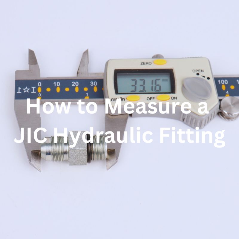
How to Measure A JIC Hydraulic Fitting
Table of Contents
Introduction
In the world of hydraulic systems, the precision with which components are measured and installed can be the difference between optimal performance and costly failures. This post delves into the specifics of measuring JIC hydraulic fittings, a critical task for ensuring the integrity of these systems. We’ll guide you through the necessary tools, steps, and best practices to accurately measure JIC fittings, aiming to provide you with the knowledge needed to execute this task flawlessly.
Defining JIC Hydraulic Fittings
JIC hydraulic fittings, standing for Joint Industry Council, are the gold standard in creating secure, leak-free connections in hydraulic systems. Originally developed for the high-pressure demands and stringent requirements of the aerospace industry, these fittings have proven their mettle by providing unmatched reliability and durability. The hallmark of JIC fittings is their 37-degree flare, which ensures a tight seal and easy assembly.
Versatility and Applications
The adaptability of JIC hydraulic fittings to various environments is a testament to their design excellence. Beyond their aerospace origins, these fittings are now integral components in a plethora of sectors. Agricultural machinery relies on them for efficient operation under rugged conditions, while industrial equipment benefits from their robust performance in high-pressure applications. This versatility not only highlights their importance across different industries but also showcases their role in ensuring the smooth and reliable operation of hydraulic systems.

Essential Measuring Tools
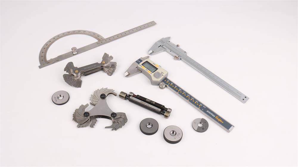
When it comes to measuring JIC hydraulic fittings, three primary tools are indispensable:
Calipers: These are the workhorses for measuring both external and internal dimensions of fittings. Digital calipers, in particular, offer high precision and ease of reading measurements, making them a favorite among professionals. They are crucial for determining the outer diameter of male fittings and the inner diameter of female fittings, ensuring that the sizes match industry standards.
Thread Gauges: The correct identification of thread pitch and size is critical for ensuring the compatibility of fittings. Thread gauges allow users to match the threads of a fitting against a known standard, ensuring that the fitting will thread correctly into its counterpart. This tool is essential for preventing cross-threading and ensuring a leak-free connection.
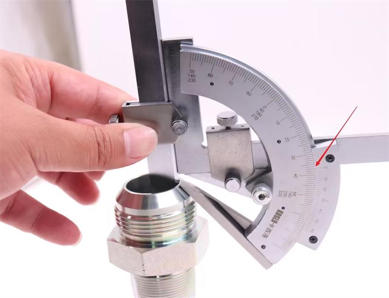
Angle Gauges: Given that JIC fittings utilize a 37-degree flare, measuring the seat angle accurately is paramount. An angle gauge helps in verifying that the seating angle matches the JIC standard, ensuring a proper seal upon connection. Incorrect angles can lead to improper sealing and potential system failures.
Step-by-Step Guide to Measuring JIC Fittings
Step 1: Identifying the Fitting Type
Before diving into measurements, it’s essential to identify the type of JIC fitting you’re dealing with. JIC fittings come in various forms, including straight, elbow, tee, and cross types, each serving different functions in a hydraulic system. Recognizing the fitting type not only facilitates a smoother measurement process but also ensures you’re applying the correct specifications for that particular design.
Step 2: Measuring Thread Size and Pitch

Measuring Thread Size
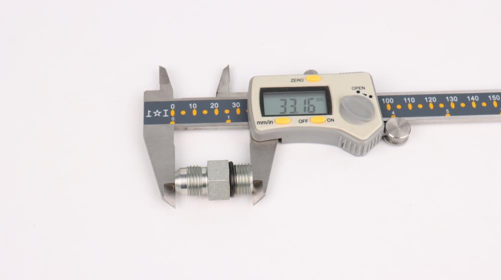
Select the Appropriate Caliper: Begin with a digital or vernier caliper that offers precision. Ensure it is zeroed out before use to guarantee accuracy.
Measure Male Threads: For male fittings, position the caliper’s jaws around the outer diameter of the threads. Ensure you are measuring the widest part, which is typically at the middle of the threads, avoiding any damaged or worn areas.
Measure Female Threads: For female fittings, insert the caliper’s tips into the fitting to measure the inner diameter. Again, aim for a measurement in the center of the thread path to avoid inaccuracies.
Record the Measurement: Take note of the measurement displayed on the caliper. This is the nominal size of the fitting, crucial for ensuring compatibility with the hydraulic system.
Measuring Thread Pitch
Select the Correct Thread Gauge: Thread gauges come with a variety of pitches. Select the one that you suspect matches the fitting’s thread pitch based on the nominal size measured earlier.
Align the Gauge with the Threads: Gently press the gauge against the fitting’s threads. The gauge should slot into the thread grooves seamlessly if it’s the correct pitch.
Verify the Match: If the gauge’s teeth align perfectly with the threads, without any gap or overlap, you’ve correctly identified the thread pitch. If the match isn’t perfect, try a gauge with a different pitch until you find the correct one.
Record the Pitch Measurement: Once the correct pitch is identified, make a note of it. This information, combined with the thread size, is crucial for identifying the exact specifications of the JIC fitting.
Step 3: Determining the Seat Angle
Select an Angle Gauge: To start, choose an angle gauge capable of accurately measuring the 37-degree seat angle. There are specialized gauges available that are specifically designed for measuring the angles of hydraulic fittings.
Prepare the Fitting: Ensure the fitting is clean and free from any debris or damage that could affect the measurement. It’s important to have a clear view of the seat area where the fitting will make contact with its counterpart.
Position the Angle Gauge: Carefully place the angle gauge against the seat of the fitting. The gauge should sit flush against the angled surface. For fittings with internal seats, ensure the gauge is inserted properly and sits evenly against the seat angle.
Verify the Angle: Look closely to confirm that the gauge aligns perfectly with the seat’s angle. A perfect match indicates a 37-degree angle. If there’s any gap or misalignment, double-check the positioning of the gauge or reevaluate the fitting’s specifications.
Adjust if Necessary: If the gauge does not sit flush, it may indicate an issue with the fitting’s angle. While JIC fittings should have a 37-degree seat angle, manufacturing variances can occur. If you suspect a discrepancy, compare with another fitting or consult with the manufacturer.
Record Your Findings: Once you’ve confirmed the seat angle, make a note of it. This information is critical for ensuring that the fitting will form a proper, leak-free seal when connected to its counterpart.
Step 4: Checking for Additional Features
Finally, inspect the fitting for any additional features that may affect its functionality or compatibility with the hydraulic system. This includes:
O-rings: Some JIC fittings include O-rings for additional sealing capabilities. Ensure these are present if required and in good condition.
Seals: Similar to O-rings, other types of seals may be part of a fitting’s design. These should also be inspected for integrity and suitability for the intended application.
Special Coatings or Materials: Depending on the application, fittings may have coatings for corrosion resistance or be made from specific materials to handle different fluids. Recognizing these features is crucial for application success.
Step 5: Common Measurement Mistakes in JIC Fitting Assessment
Using Worn-Out Tools
Problem: Over time, measuring tools can wear down, leading to inaccurate readings. This is particularly true for tools like calipers and thread gauges, which rely on precise contact points to measure dimensions accurately.
Solution: Regularly inspect your tools for signs of wear, especially on the measuring surfaces. Consider replacing tools that show significant wear or have become unreliable. Implementing a scheduled calibration can also help ensure ongoing accuracy.
Incorrect Tool Selection
Problem: Choosing the wrong tool for the job can lead to measurement errors. For example, using a standard angle gauge instead of one designed for hydraulic fittings might not provide the accuracy needed for determining the correct seat angle.
Solution: Always use tools that are appropriate for the specific measurement task at hand. Research and invest in specialized tools designed for hydraulic fitting measurements, such as specific thread gauges for hydraulic threads and angle gauges with a 37-degree measurement capability.
Overlooking Critical Dimensions
Problem: Failing to measure all necessary dimensions of a fitting can result in compatibility issues, leading to leaks or connection failures. This can happen if one focuses solely on thread size, neglecting other critical aspects like the seat angle or the presence of additional sealing features.
Solution: Develop a comprehensive checklist of dimensions and features that need to be measured for each fitting type. Ensure that every measurement is taken and recorded before proceeding. This systematic approach prevents critical details from being overlooked.
Not Double-Checking Measurements
Problem: Even experienced professionals can make mistakes. A single incorrect measurement can have a domino effect, causing significant issues down the line.
Solution: Always double-check your measurements, especially if the first measurement seems off or if you’re working with a critical component. Taking the time to verify your measurements can save time, money, and frustration in the long run.
Neglecting Calibration
Problem: Measurement tools that are not regularly calibrated can drift from their original settings, leading to inaccurate readings.
Solution: Implement a regular calibration schedule for all measurement tools. This ensures that they remain accurate and reliable over time. Many manufacturers offer calibration services, or you can use certified calibration weights and standards to perform calibrations in-house.
Step 6: Regular Maintenance Practices for JIC Fittings
Maintaining the integrity of hydraulic systems involves diligent attention to the condition and compatibility of JIC fittings. Regular maintenance not only extends the lifespan of these systems but also enhances their performance and reliability. Key maintenance practices include:
Inspecting for Wear and Tear
Routine Checks: Schedule regular inspections of all hydraulic fittings within the system. Look for signs of wear, such as thread damage, corrosion, or deformation of the fitting’s body or flared end.
Preventive Replacement: If wear is detected, replace the fittings before failure occurs. This preemptive approach prevents system downtime and potential safety hazards.
Ensuring Correct Tightening
Torque Specifications: Adhere to the manufacturer’s torque specifications when installing or maintaining fittings. Over-tightening can damage threads and under-tightening can lead to leaks.
Use Proper Tools: Employ torque wrenches to achieve the correct tightness, ensuring a secure and leak-free connection.
Replacing Damaged Components
Immediate Action: Damaged or compromised fittings should be replaced immediately to maintain system integrity.
Compatibility Checks: When replacing fittings, ensure the new components are fully compatible with the existing system. This includes verifying the size, thread pitch, and seat angle.
Troubleshooting Common Issues
Addressing common issues within hydraulic systems often starts with a thorough assessment of the JIC fittings. Understanding potential problems and their solutions is crucial for efficient troubleshooting.
Leaks at Connection Points
Cause: Leaks can result from improper fitting selection, incorrect installation, or wear and tear.
Solution: Re-examine the fitting for correct size, thread pitch, and seat angle. Ensure it’s properly installed and replace if necessary.
System Pressure Drops
Cause: A drop in system pressure may indicate a loose or damaged fitting.
Solution: Inspect all fittings for proper tightness and integrity. Replace fittings where necessary and re-check system pressure once corrections are made.
Fitting Corrosion
Cause: Exposure to harsh environments can lead to fitting corrosion, compromising system reliability.
Solution: Replace corroded fittings immediately. Consider using fittings made from materials better suited to the operating environment for future installations.
JIC 37°vs SAE 45°Hydraulic fittings
Key Differences
Sealing Angle: The most apparent difference between JIC and SAE 45-degree fittings is the angle of the flare seating surface. JIC fittings use a 37-degree flare, while SAE 45-degree fittings use a 45-degree flare.
Interchangeability: JIC fittings offer greater interchangeability across different systems and manufacturers due to the standardization of the 37-degree flare design. SAE 45-degree fittings have more limited compatibility and require matching components with the same 45-degree design.


How to Identify JIC vs. SAE 45-Degree Fittings
Measure the Seat Angle: Using an angle gauge, measure the angle of the fitting’s seat. A 37-degree angle indicates a JIC fitting, while a 45-degree angle points to an SAE fitting.
Inspect the Thread Standard: Comparing the thread standards can also aid in identification. If it follows the UN/UNF standard with a 37-degree flare, it’s likely a JIC fitting. If the fitting has a 45-degree flare, check for the SAE thread standard.
Look for Markings: Some fittings are marked with their specifications, including the seat angle or the standard they conform to (JIC or SAE). While not all fittings are marked, those that are can provide a quick way to identify them.
Use Fitting Identifiers: There are tools and charts available designed to help identify hydraulic fittings by comparing their physical characteristics against known standards.
Conclusion
Accurate measurement of JIC hydraulic fittings plays a pivotal role in maintaining the reliability and efficiency of hydraulic systems. By grasping the significance of these fittings, utilizing appropriate tools, and adhering to a detailed measurement protocol, professionals can guarantee the seamless operation of their systems. This attention to precision helps in minimizing potential leaks and enhancing overall performance, ensuring that hydraulic systems meet the demands of their applications effectively. Through diligent practice and an understanding of the nuances involved in measuring and identifying hydraulic fittings, one can uphold the integrity and functionality of hydraulic systems, contributing to their longevity and reliability.


