Quickly Identify Hydraulic Fittings

Quickly Identify Hydraulic Fittings

Quickly Identify Hydraulic Fittings: What Should You Do?

Table of Contents

Introduction

Misidentification can result in the installation of incompatible or inadequate fittings, leading to leaks, system inefficiencies, or worse, catastrophic failures. Thus, technicians and engineers must be adept at quickly and accurately identifying various types of fittings to ensure they match the specifications and demands of their systems. This article aims to arm professionals with practical tips and essential tools for the swift identification of hydraulic fittings in various field settings.

Types of Hydraulic Fittings

Hydraulic fittings play a pivotal role in connecting components within hydraulic systems, ensuring fluid flows efficiently and without leaks under high pressure. Understanding the types, their applications, and identification tips is crucial for professionals who handle hydraulic machinery.

Hydraulic Hose Fittings

Description and Visual Identification Tips:

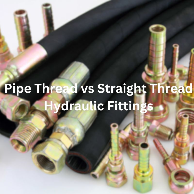
Hydraulic hose fittings are designed to connect hoses to components like hydraulic cylinders, valves, and pumps. They typically feature a barbed end to grip the inside of a hose and may have a threaded or flanged end to connect to the system. These fittings are often made from strong metals like steel or brass to withstand high pressures. Visually, hose fittings are recognized by their robust construction and multiple ridges or barbs.

Common Applications and Examples:

These fittings are used extensively in mobile hydraulics, construction equipment, and industrial machinery. For example, an excavator uses hydraulic hose fittings to connect its hydraulic hoses to the hydraulic pump and cylinders, facilitating the smooth operation of its moving parts.

Hydraulic Adapters

Functionality and Distinguishing Features:

Hydraulic adapters are used to connect different types of fittings and are essential for transitioning between various thread types or sizes. They often come in shapes such as straight, elbow, or tee, with male and female ends of differing types. Adapters can be identified by their geometric shapes and the presence of different threading on each end.

Material Types and Their Implications:

Materials commonly used for adapters include stainless steel, carbon steel, and brass. The choice of material affects the fitting’s corrosion resistance and suitability for different fluids and environmental conditions. Stainless steel adapters are preferred in corrosive environments, while brass is typically used for lower pressure settings.

Quick Couplings

How They Work and Common Uses:

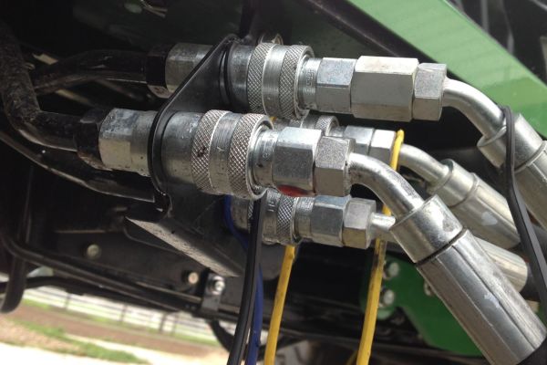
Quick couplings, or quick-connect fittings, allow for fast connection and disconnection of hydraulic lines without the need for tools. These fittings generally have a male part (the plug) and a female part (the socket) that snaps together with a simple push-pull action. They are equipped with seals to prevent leaks during disconnection and connection.

Quick Identification Guide for Rapid Deployment:

Quick couplings are identifiable by their push-pull locking mechanism and the presence of a release sleeve on the socket. They are widely used in applications requiring frequent disassembly or where flexibility is needed, such as in agricultural implements or industrial machinery maintenance.

Banjo Fittings

Characteristics and Unique Identification Markers:

Banjo fittings are named for their distinctive shape that resembles a banjo. These fittings have a hollow bolt passing through a perforated circular plate, allowing fluid to flow through the bolt. They are easily identified by this unique structure.

Usage Scenarios and Compatibility:

Banjo fittings are commonly found in automotive fuel, oil, and hydraulic brake systems where space is limited and bending of hoses is required. Their design allows for a compact connection without excessive bending of the hydraulic hose.

Ferrule Fittings

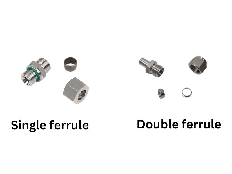
Detailed Description and How They Differ from Other Fittings:

Ferrule fittings consist of a circular clamp (ferrule) that tightens around the hose to secure it to the fitting body. These are typically used with softer hoses to provide a tight seal by compressing the hose between the ferrule and the fitting body.

Importance in Hydraulic Systems:

The ferrule creates a seal that can withstand high pressures, making these fittings essential for high-pressure applications like chemical processing or oil and gas delivery. They differ from other fittings in that they provide a permanent, leak-proof seal that is crucial for maintaining system integrity.

Identification Marks on Fittings

Accurate identification of hydraulic fittings in the field can significantly streamline maintenance and setup processes. Manufacturers often utilize specific marking systems on fittings to aid in this identification. Two common methods include hexagonal markings and cap identifications.

Hexagonal Markings

Nut identify

Explanation of Markings Found on Hexagonal Fittings:

Hexagonal fittings often feature small notches or markings on their hexagonal surfaces. These markings are not merely decorative; they provide essential information about the fitting’s standard and specifications. Typically, these are machined into the fitting during manufacturing and are designed to be easily visible to aid quick identification.

Decoding the Meaning of Single vs. Double Notches:

Single Notch: Generally indicates that the fitting adheres to British standards (BSPP, BSPT). These fittings are commonly used in applications requiring a reliable seal in the presence of high fluid pressure.

Double Notch: Indicates that the fitting conforms to American standards (NPT, JIC). This differentiation is crucial as mixing components from different threading standards can lead to leaks or thread damage.

Understanding these markings can prevent costly errors in system assembly, ensuring compatibility and functionality.

Cap Identification

cap identification

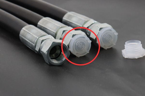
How to Use Markings on Fitting Caps for Identification:

Manufacturers may also place identification marks on the caps of fittings. These caps protect the fitting during shipping and handling but can also serve as a quick reference point for technicians. Markings on caps can include the type of thread, size, and sometimes the material of the fitting. For example, a cap might be marked with “M16x1.5” indicating a metric thread with a diameter of 16 mm and a pitch of 1.5 mm.

Visual Examples for Clarity:

To aid in understanding, visual examples of cap markings include:

A cap marked with “SS” typically denotes stainless steel material, suggesting suitability for corrosive environments.

A cap with “3/8 NPT” indicates a 3/8 inch National Pipe Tapered thread, common in general industrial applications.

These cap identifications, combined with other markings, allow field technicians to quickly verify fitting characteristics without the need for additional tools or reference materials, streamlining maintenance and ensuring system integrity.

Thread Appearance

The thread type of a hydraulic fitting is crucial for ensuring compatibility and seal integrity within hydraulic systems. Different industries and regions might favor specific thread types based on standards and requirements. Recognizing these thread types visually can save time and prevent the common pitfalls of mismatching components.

Overview of Common Thread Types

Characteristics of Common Thread Types:

JIC (Joint Industry Council): JIC threads are characterized by their 37-degree flare seating surface and are often used in high-pressure applications. They are similar in appearance to AN (Aerospace Number) fittings used in military applications.

SAE (Society of Automotive Engineers): SAE threads are also flared (usually at 45 degrees) and are typically used in automotive and heavy equipment applications. They are robust and designed for medium to high-pressure conditions.

NPT (National Pipe Tapered): NPT threads are tapered and designed to provide a tight seal through the threading itself, making them ideal for plumbing applications. They require thread sealant or Teflon tape to ensure a leak-proof connection.

BSP (British Standard Pipe): BSP threads can be either parallel (BSPP) or tapered (BSPT). BSPP threads are commonly found in European equipment and require a bonded seal, while BSPT threads create a mechanical seal through thread engagement.

Metric: These threads are specified by the thread’s outer diameter and the pitch in millimeters, common in most non-North American equipment. Metric threads are straightforward and do not usually require flaring.

ORFS (O-Ring Face Seal): These have a flat sealing surface with an O-ring in a groove on the face of the fitting, providing an excellent seal. They are widely used in hydraulic systems where leakage is a critical concern.

Visual Comparison and Identification Tips:

Visually, JIC fittings can be distinguished by their shiny, metallic flare, while SAE fittings generally have a more pronounced thread and flared angle. NPT fittings taper towards the end, making them visually narrower at the tip than at the base. BSP threads are very uniform and symmetrical. Metric threads look very similar to BSP but are measured in metric units. ORFS fittings are recognizable by their flat face and visible O-ring.

Using Thread Charts and Gauges

How to Use Thread Charts Effectively:

Thread charts are essential tools for identifying thread types and sizes. These charts provide detailed illustrations and specifications of different threads. To use a thread chart effectively, measure the outer diameter of a male thread or the inner diameter of a female thread, then compare these measurements with the chart to determine the thread type and size.

Recommended Thread Gauges for Field Use:

Caliper-style Thread Gauge: Allows for quick and accurate measurement of the diameter and pitch of a thread.

Screw Pitch Gauges: Useful for determining the pitch of the thread by matching the teeth on the gauge with the thread.

Combination Gauges: These gauges combine features for measuring diameter, pitch, and thread type in one tool.

Carrying these gauges in the field allows technicians to quickly verify the thread type of a fitting, ensuring that replacements or repairs are done with the correct components, thus maintaining system integrity and function.

Determining Thread Angles

Thread angles are critical features in the identification and compatibility of hydraulic fittings, as they influence the type of seal formed and the fitting’s suitability for specific pressures and applications. Understanding how to measure and identify these angles can prevent equipment failures and maintain system integrity.

BSP vs NPT threads Topa

Thread Angle Identification

BSP (British Standard Pipe): BSP threads can be either parallel or tapered, but the thread angle is consistently set at 55 degrees. This angle helps in forming a tight seal when used with appropriate sealing washers or bonding compounds, particularly in high-pressure systems common in Europe.

Metric Threads: Metric threads, used predominantly outside of North America, generally feature a thread angle of 60 degrees. This angle is common across most metric fittings, making them slightly sharper compared to BSP threads. They are straightforward to identify due to their widespread use in automotive and industrial applications globally.

NPT (National Pipe Tapered): NPT threads have a unique feature of a 60-degree thread angle but are tapered, which allows the threads to form a seal as they are tightened. The tapering and angle are designed to mesh tightly as the male and female threads are screwed together, using the thread itself to form a seal, which is enhanced by thread sealants.

Practical Tips on Measuring and Identifying Thread Angles

Use a Thread Gauge: The most straightforward method to determine thread angles is to use a thread gauge, which can directly measure the angle formed at the thread’s peak. Simply place the gauge against the thread; if it fits perfectly, you have found the correct angle.

Calipers and Micrometers: For a more precise measurement, use calipers or micrometers to measure the outer and inner diameters of the threads. Once you have these measurements, refer to a thread identification chart to determine the angle based on known standards.

Visual Comparison: Often, a trained eye can distinguish between the slightly different angles of Metric (60 degrees) and BSP (55 degrees) threads through visual inspection, especially when they have samples for comparison. This method is quick and useful in field conditions where precise instruments may not be available.

Consult Technical Specifications: When possible, consult the technical specifications of the fitting. Manufacturers often provide detailed diagrams and specifications, including thread angles, which can be invaluable for verification.

When to Contact the Manufacturer

Unusual or Custom Fittings: If the fitting in question is not standard or appears to be custom-made for specific equipment, manufacturer insights can provide necessary specifications and replacement details.

Obsolete or Discontinued Parts: When dealing with older or discontinued models, the manufacturer can often suggest modern equivalents or provide sources for obtaining rare parts.

Safety-Critical Applications: For fittings used in critical safety applications, such as aerospace or chemical processing, confirming specifications with the manufacturer ensures compliance with safety standards and regulatory requirements.

Complex Assemblies: In systems with complex integration of various fitting types, manufacturers can offer assembly diagrams and compatibility guidance to avoid errors in reassembly after maintenance or repair.

Conclusion

The ability to quickly and accurately identify hydraulic fittings in the field is a critical skill for technicians and engineers working in the maintenance and assembly of hydraulic systems. Professionals should keep abreast of industry standards and new developments. The tips and strategies outlined in this guide are designed not only to improve individual skills, but also to foster a culture of precision and safety that benefits the industry as a whole. If you are still in any doubt, feel free to contact Topa!

FAQ

What are the most common types of hydraulic fittings?

The most common types include JIC (Joint Industry Council), SAE (Society of Automotive Engineers), NPT (National Pipe Tapered), BSP (British Standard Pipe), Metric, and ORFS (O-Ring Face Seal).

How can I visually distinguish between JIC and SAE fittings?

JIC fittings have a 37-degree flare, and SAE fittings typically have a 45-degree flare. The difference in the angle of the flare is visually noticeable when compared side by side.

What is the best way to determine the thread type of a hydraulic fitting?

Use a thread gauge to measure the pitch and diameter of the thread. Comparing these measurements with a thread identification chart can confirm the type.

Can NPT and BSP threads be interchanged?

No, NPT and BSP threads should not be interchanged. NPT threads have a different taper and pitch compared to BSP threads, which can lead to leaks and thread damage if forced together.

Why is it important to identify hydraulic fittings correctly?

Correct identification ensures compatibility and seal integrity, which are crucial for preventing leaks and maintaining system pressure and efficiency.

What tools are essential for identifying hydraulic fittings in the field?

Essential tools include calipers for measuring dimensions, thread gauges for identifying thread types, and possibly a reference book or mobile app with visual identifiers.

How a Hydraulic System Works Efficiency & Optimization

How a Hydraulic System Works

How a Hydraulic System Works: Efficiency & Optimization

Introduction

Hydraulic systems are an integral part of modern machinery, transmitting power through fluid pressure and flow. Central to maximizing the potential of a hydraulic system are the twin principles of efficiency and optimization. Efficiency in a hydraulic system means achieving maximum output with minimum energy loss. Optimization, on the other hand, is the fine-tuning of system components and operations to achieve optimal performance. This paper will take an in-depth look at the fundamental aspects of hydraulic systems, highlighting their role in a variety of industries and the importance of optimizing these systems for efficiency.

Understanding Hydraulic Systems

Introduction to Hydraulic Principles

Hydraulic systems operate on a simple yet powerful principle: the ability to transmit force through a fluid, typically oil, under pressure. This is based on Pascal’s Law, which states that pressure exerted anywhere in a confined incompressible fluid is transmitted equally throughout the fluid such that it acts with equal force on equal areas, in all directions. This principle is foundational in hydraulic systems, enabling the exertion of high forces or the execution of precise movements in heavy machinery.

Exploring Key Components

Hydraulic Pumps: These are the heart of the hydraulic system, responsible for moving the fluid from the reservoir through the system. Different types of pumps include gear pumps, which are known for their durability and simplicity; vane pumps, offering variable displacement options; and piston pumps, known for their high pressure and efficiency.

Valves: Valves in a hydraulic system control the flow and direction of the hydraulic fluid. Directional control valves manage the path of the fluid, whereas pressure relief valves protect the system from excessive pressure. Control valves adjust the flow rate and thereby the speed of the actuators.

Actuators: Hydraulic actuators convert the energy of the hydraulic fluid into mechanical motion. Hydraulic cylinders provide linear motion, while hydraulic motors offer rotary motion, enabling the operation of various types of machinery.

Reservoirs: The reservoir holds the hydraulic fluid. Its roles include not just storage, but also cooling and filtering the fluid. Maintaining clean and temperature-controlled fluid is essential for the system’s performance and longevity.

System Dynamics and Component Interplay

In a hydraulic system, all components must work in concert for efficient operation. The pump sends hydraulic fluid into the system under pressure. This fluid travels through valves, which direct it to various actuators based on the operation’s requirements. The actuators then convert this hydraulic energy into mechanical energy, performing the needed work, whether it’s lifting, pushing, or rotating. After transmitting its energy, the fluid returns to the reservoir, where it is prepared for another cycle.

Hydraulic Fluids

The choice of hydraulic fluid is critical as it affects the efficiency and safety of the entire system. Different types of fluids are used based on the operational environment and machinery requirements. The fluid must have suitable viscosity for the system’s temperature range, good lubricating properties, and must be resistant to forming foam and emulsions.

hydraulic fluid Topa

Control Systems and Feedback Loops

Modern hydraulic systems often integrate electronic control systems and feedback loops. These systems allow for precise control of the hydraulic actuators, leading to more efficient, responsive, and sophisticated machinery operation. They can adjust the flow and pressure of the fluid dynamically, responding to the immediate requirements of the machinery and its load, thereby optimizing the performance and energy usage of the system.


Factors Affecting Efficiency in Hydraulic Systems

Efficiency in hydraulic systems is significantly affected by several factors including the properties and selection of hydraulic fluid, system design and layout, and the quality and compatibility of components.

Hydraulic Fluid Properties and Selection

The hydraulic fluid is a key element in any hydraulic system. Its properties directly impact the system’s efficiency. Fluid viscosity is crucial; too thick, and it will resist flow and increase the energy needed to pump it, too thin, and it will fail to lubricate effectively and lead to increased wear. The fluid should also have good lubrication properties to reduce friction and wear in the system. Additionally, its chemical composition should be stable under the range of operating temperatures and pressures. Selecting the right hydraulic fluid involves considering the system’s operational environment, including temperature extremes and potential contaminants.

Role of System Design and Layout

Efficient system design optimizes the flow of hydraulic fluid and minimizes energy losses. This involves proper sizing of components, including pipes, hoses, and valves, to ensure adequate flow while avoiding excessive pressure drops. The layout of the system should also be considered to prevent heat build-up and to facilitate maintenance and inspection. Design considerations also include the placement of components to minimize the length of hydraulic lines, reducing the potential for leaks and inefficiencies.

Importance of Component Quality and Compatibility

The quality of components in a hydraulic system plays a vital role in its efficiency. Higher-quality components tend to have better tolerances, more robust materials, and better resistance to wear and tear. Compatibility of components is also crucial. Components not designed to work together can cause inefficiencies in the system due to mismatches in size, pressure ratings, or material incompatibilities. Regular inspection and maintenance are key to ensuring the components function well together over the life of the system.

Each of these factors plays a substantial role in determining the efficiency of a hydraulic system. By understanding and addressing them, one can ensure the system operates at its optimal performance, reducing energy usage and increasing the lifespan of the components.

Common Challenges in Hydraulic Systems

Hydraulic systems are prone to several challenges that can affect their performance, efficiency, and longevity.

Leaks and Contamination

One of the most common issues in hydraulic systems is leaks. These can occur due to wear and tear on seals and hoses or through faulty connections. Leaks not only lead to a loss of hydraulic fluid but can also introduce contaminants into the system. Contamination, particularly by water, air, or particulate matter, can severely affect the system’s performance. It leads to corrosion, increased wear on components, and can significantly reduce the efficiency of the system.

Pressure Fluctuations and Overheating

Another challenge is the management of pressure fluctuations. These can arise from various factors, including air entrapment in the fluid or issues with the hydraulic pump. Inconsistent pressure can result in erratic system performance and can be damaging to the machinery. Overheating is a related concern and can be caused by inadequate cooling, environmental factors, or operating the system beyond its capacity. Overheating can degrade the hydraulic fluid, leading to reduced performance and potential damage to the system.

Wear and Tear of Components

Regular use of hydraulic systems inevitably leads to wear and tear of its components. This is a natural process but can be accelerated by factors such as contamination, inadequate maintenance, or operating the system in extreme conditions. Wear and tear can decrease the efficiency of the system and, if not addressed, can lead to system failure.

Proactive maintenance and monitoring of hydraulic systems are essential in addressing these challenges. Regular checks can identify potential leaks and contamination early, pressure levels can be monitored to ensure stable operation, and components can be inspected for signs of wear and tear.

Strategies for Optimization

Enhancing the efficiency of hydraulic systems is crucial for both performance and sustainability. This involves a systematic approach that includes regular maintenance and monitoring, employing advanced technological solutions, and retrofitting or upgrading existing systems to meet current standards of efficiency and performance.

Regular Maintenance and Monitoring

Comprehensive maintenance is the cornerstone of hydraulic system optimization. This involves regular inspections, proactive replacement of worn or damaged components and ensuring the integrity of seals and hoses to prevent leaks. Regularly changing hydraulic fluids and filters is also essential to maintain the cleanliness and efficiency of the system. Monitoring entails checking system pressures, temperatures, and fluid levels to detect any signs of malfunction or inefficiency early on.

Advanced Technologies for System Monitoring and Diagnostics

The integration of advanced technologies plays a pivotal role in the optimization of hydraulic systems. The use of sensors and real-time monitoring equipment allows for the continuous tracking of system performance. These technologies can provide valuable data on the system’s operational parameters, enabling predictive maintenance and immediate corrective actions. Diagnostic software and tools facilitate the quick identification of potential issues, reducing downtime and preventing major breakdowns.

Retrofitting and Upgrading Existing Systems

Upgrading and retrofitting existing hydraulic systems with new technology and components can significantly enhance their efficiency. This could involve installing more efficient pumps and motors, upgrading control valves for better flow regulation, or integrating advanced filtration systems. Retrofitting older systems with modern electronics and control systems can also provide finer control, increased precision, and improved energy efficiency. These upgrades not only improve performance but also extend the lifespan of the hydraulic systems, making them more sustainable and cost-effective in the long run.

In conclusion, optimizing hydraulic systems through these strategies is essential for maintaining their operational efficiency, reducing environmental impact, and minimizing operational costs. By combining regular maintenance, advanced technology, and strategic upgrades, hydraulic systems can achieve optimal performance and reliability.

Conclusion

Wrapping up, the exploration of hydraulic systems has highlighted their pivotal role across various industries. We’ve navigated through the intricacies of these systems, from understanding their basic components to delving into the advancements in hydraulic fluid technology. The significance of skilled operation and the impact of emerging technologies in enhancing efficiency were underscored. As we look ahead, the trends point towards smarter, more sustainable hydraulic systems. This journey reaffirms the necessity of continual efficiency optimization in hydraulic systems, balancing operational needs with environmental stewardship.


Conclusion

Hydraulic systems typically consist of a reservoir tank, hydraulic pump, pipes and hoses, motor, valves, actuators, and filters.

Hydraulic systems operate by using a fluid (usually oil) pumped from a reservoir through pipes and valves to an actuator, where it exerts force on a piston, creating motion .

The two primary types are open-loop and closed-loop systems. Open-loop systems do not maintain pressure when idle, while closed-loop systems maintain pressure and typically utilize a feed or charge pump.

Extreme temperatures can negatively impact hydraulic systems; high temperatures can decrease the viscosity of hydraulic oil, affecting its lubrication ability, while low temperatures can increase oil viscosity and make the system less efficient​.

Regular maintenance includes checking fluid levels and quality, inspecting for leaks, and changing filters to maintain system efficiency and prevent malfunctions.

Due to the high pressure under which hydraulic systems operate, it’s crucial to handle them carefully, adhere to safety guidelines, and perform regular checks to prevent accidents.

Common troubleshooting steps include checking for leaks, ensuring proper fluid levels, and inspecting components for wear and damage.

Factors include the required oil flow rate, desired working pressure, and the hydraulic cylinder’s oil volume displacement.

Hydraulic cylinder failures can often be attributed to side loading, which misaligns the cylinder and creates uneven forces on the piston rod.

Single-acting cylinders use hydraulic fluid for motion in one direction only, while double-acting cylinders use fluid for both extending and retracting movements​.

How to identify NPT hydraulic fittings

How to Identify NPT Hydraulic Fittings?

How to Identify NPT Hydraulic Fittings?

Introduction

NPT (National Pipe Taper) hydraulic fittings are designed with tapered threads and are essential for creating leak-proof connections in a wide range of machinery and equipment. The unique taper of NPT fittings allows for a tighter seal when screwed into their counterparts. This guide is designed to provide a thorough understanding of NPT fittings, from their characteristics and applications to best installation practices and safety precautions, to ensure that readers have a better understanding of hydraulic NPT fittings.

Understanding NPT Fittings

NPT, which stands for National Pipe Taper, is a U.S. standard that specifies the design of tapered threads used to seal pipes and fittings. This design is crucial in hydraulic systems, where creating tight, leak-proof seals is essential for maintaining system pressure and fluid integrity. NPT fittings are widely used in various applications, including in the construction, manufacturing, and automotive industries, where hydraulic systems play a critical role. Their ability to create a seal that can withstand high pressure makes them indispensable in systems that transport fluids or gases.

Historical Background and Standardization

The standardization of NPT fittings was a response to the need for a consistent and reliable way to connect piping and components in hydraulic systems. This standardization has its roots in the early development of plumbing and engineering, where the efficiency and safety of fluid transport systems were paramount. Over the years, the specifications for NPT fittings have been refined to meet the evolving demands of hydraulic systems, ensuring they provide reliable seals under a wide range of conditions.

Key Characteristics

Taper Angle: The taper angle of NPT threads is precisely 1° 47′ 24″ (or 1.7899°), a specification that ensures a tighter fit as the fitting is screwed into its mating component. This angle allows the threads to interlock more effectively, increasing the pressure that the connection can withstand before leaking. The taper creates a seal by the interference between the male and female threads, which compresses and deforms slightly, filling any gaps that could lead to leaks.

Thread Count: NPT threads are characterized by their thread count, which is the number of threads per inch. This count varies depending on the diameter of the fitting, with larger diameters generally having fewer threads per inch. The thread count is crucial because it influences the compatibility of fittings and the quality of the seal they can achieve. A higher thread count can provide a finer thread, which may be better suited for applications requiring precise control over the connection’s tightness.

The Physical Characteristics of NPT Fittings

Thread Shape and Taper

The defining feature of NPT (National Pipe Taper) fittings is their conical thread shape, which facilitates a deeper engagement between the male and female threads over the length of the fitting. This characteristic design not only enhances the mechanical strength of the connection but also significantly improves the seal’s integrity as force is applied. The taper angle, precisely calculated, allows for the threads to interlock more snugly as they are tightened, compressing against each other to form a seal that is resistant to fluid or gas leaks.

NPT Fitting drawing Topa

Measurement Techniques

Diameter: The diameter of NPT threads is a crucial measurement, as it dictates the size of the fitting required for a specific application. It is typically measured across the outermost edges of the thread. This measurement helps in determining the nominal size of the pipe and fitting, ensuring compatibility between components in the hydraulic system.

Thread Pitch: Another critical measurement is the thread pitch, which refers to the distance from one thread to the next. This is usually measured in threads per inch (TPI). The thread pitch is essential for identifying the thread size and ensuring that the fitting will correctly mate with its counterpart. A correct thread pitch is vital for achieving a tight seal, as mismatched threads can lead to leaks or damage to the threads themselves.

Tapered Appearance

The tapered design of NPT threads is not just a distinctive physical characteristic but also a functional feature that ensures a tight seal. The taper allows the threads to engage more deeply as they are screwed together, creating a pressure-tight seal that improves with increased force. This visual cue can be quickly identified by observing the narrowing of the threads from one end to the other, distinguishing NPT fittings from parallel thread fittings which do not have this feature.

Step-by-Step NPT Thread Identification

Measuring the Outer Diameter:

Tools Needed: Calipers are the preferred tool for this measurement due to their precision.

Process: Place the calipers around the largest point of the thread to obtain an accurate outer diameter measurement. This dimension is critical for identifying the nominal pipe size, as NPT thread sizes are often referred to by the nominal pipe size they are intended to seal.

Counting the Thread Pitch:

Tools Needed: A thread gauge is specifically designed for this task, offering a range of graduated teeth corresponding to different thread pitches.

Process: Match the teeth of the gauge with the threads of the fitting until a perfect alignment is found, indicating the thread pitch in threads per inch (TPI). This step is vital for ensuring that the thread pitch matches that of the component it will connect to, as mismatched pitches can prevent proper sealing and may damage the threads.

Comparing Dimensions:

Process: Once the outer diameter and thread pitch have been determined, these measurements should be compared to standard NPT size charts. These charts provide the nominal sizes and TPI for standard NPT threads, allowing for the identification of the thread type.

Importance: This comparison is essential for selecting the correct fitting for the application, ensuring that the components will properly mate and maintain the system’s integrity and performance.

Comparison with Other Hydraulic Fitting Types

Understanding the differences and similarities between NPT fittings and other common hydraulic fitting types such as JIC, ORFS, and BSPP is crucial for selecting the appropriate connection for hydraulic systems. Each fitting type has unique characteristics that make it suitable for specific applications.

JIC (Joint Industry Council) Fittings

JIC fittings are recognized for their 37° flare seating surface, which contrasts sharply with the tapered threads of NPT fittings. This flare provides a metal-to-metal seal that is both robust and reusable.

ORFS (O-Ring Face Seal) Fittings

ORFS fittings use a flat sealing surface along with an O-ring located in a groove on the face of the fitting. This design offers a high-integrity seal, reducing the risk of leaks. Unlike the metal-to-metal seal of NPT and JIC fittings, the ORFS’s O-ring provides a more forgiving seal that compensates for surface imperfections. ORFS fittings are commonly used in applications where leaks cannot be tolerated, such as in environmentally sensitive or high-pressure systems. Their reliable seal makes them suitable for both static and dynamic applications.

BSPP (British Standard Pipe Parallel) Threads

BSPP threads are parallel, not tapered like NPT threads, and they typically include an O-ring or bonded washer for sealing. This characteristic enables a seal on the threads’ periphery rather than through thread engagement. BSPP fittings are often found in applications where a secure seal is needed but where the fitting will not be subjected to the same kind of mechanical strain that might favor a tapered thread. They are commonly used in lower-pressure fluid systems and in many hydraulic systems outside of North America.

JIC vs NPT vs BSP

Key Considerations in Selection

Seal Integrity: When selecting between these fitting types, the critical consideration is the type of seal required. NPT’s tapered threads provide a solid mechanical lock, but they may require sealants to ensure a leak-proof connection. In contrast, JIC and ORFS fittings provide metal-to-metal and O-ring seals, respectively, which can offer more reliable sealing without additional materials.

Pressure Ratings: The application’s pressure demands can also dictate the fitting choice. JIC and ORFS fittings are generally suitable for higher pressure systems than NPT or BSPP, though specific ratings can vary by manufacturer and material.

Reusability: For applications requiring frequent disassembly, JIC and ORFS fittings may offer advantages in terms of reusability compared to NPT fittings, which can deform upon re-tightening.

Installation Tips and Best Practices

Installation Guide

The proper installation of NPT hydraulic fittings is crucial for the performance and longevity of hydraulic systems. Here’s a step-by-step guide to ensure optimal installation:

Cleaning Threads: Begin with clean threads on both the male and female components. Any debris, dirt, or metal shavings can compromise the seal, leading to leaks. Use a clean, lint-free cloth to wipe down the threads.

Applying Appropriate Sealant: While NPT fittings are designed to create a tight seal, the application of an appropriate thread sealant can prevent potential leaks. Teflon tape or liquid pipe thread sealants are commonly used. When applying Teflon tape, wrap it in the direction of the thread’s turn, typically 2-3 wraps are sufficient, ensuring the tape does not extend over the end of the fitting to avoid entering the hydraulic system.

Tightening to Correct Torque: Over-tightening can cause damage to the threads or the fitting itself, leading to cracks or splits, while under-tightening may result in leaks. It is essential to tighten NPT fittings to the manufacturer’s recommended torque settings. A torque wrench can be used to achieve the correct torque.

Troubleshooting Common Issues

Even with careful installation, issues can arise. Here are common problems and solutions:

Leaks: If a leak is detected, first check if the fitting is tightened to the correct torque. If it continues to leak, disassemble, inspect for damage or improper sealant application, and reassemble with fresh sealant.

Cross-threading: This occurs when threads are misaligned during installation, causing damage. If you encounter resistance when threading by hand, stop and realign. Cross-threaded fittings should be replaced to ensure integrity.

Over-tightening: Can lead to thread or fitting damage. If over-tightening is suspected, inspect the fitting and threads for damage. Replace if necessary and reinstall to the proper torque specification.

Under-tightening: Results in insufficient pressure to form a complete seal. If a fitting is found to be under-tightened, carefully tighten to the recommended torque, checking for leaks after adjustment.

Maintenance and Inspection

Regular maintenance and inspection are critical to ensuring the longevity and reliability of NPT hydraulic fittings within hydraulic systems. Establishing a routine for checking these components can prevent premature failure, avoid costly downtimes, and maintain system integrity. Here are key practices for maintaining and inspecting NPT fittings:

Scheduled Checks

Frequency: The frequency of inspections should be based on the system’s operational intensity and the environmental conditions to which it is exposed. High-pressure systems or those in harsh environments may require more frequent checks.

Wear and Damage: Look for signs of wear, such as thread damage, cracks, or corrosion on the fittings. Even minor damage can compromise the fitting’s integrity and the system’s pressure-holding capabilities.

Leak Detection: Regularly check for leaks around NPT fittings. Use appropriate methods such as visual inspection, pressure tests, or leak detection fluids. Early detection of leaks can prevent significant system damage and fluid loss.

Preventive Measures

Cleaning: Keep the area around fittings clean from debris and contaminants that could enter the system during maintenance or component replacement.

Lubrication: Where applicable, ensure that moving parts connected to or including fittings are adequately lubricated to prevent seizing or wear.

Replacement of Worn Out Parts: Replace any fittings showing signs of wear or damage immediately. Using damaged fittings can lead to system failures.

Safety Tips

Depressurize the System: Always ensure the hydraulic system is fully depressurized before starting any work on it. Accidental release of pressurized fluid can cause serious injuries.

Check for Leaks Safely: Use appropriate methods to check for leaks, such as paper or ultrasonic leak detectors. Avoid using your hands, as hydraulic fluid under pressure can penetrate the skin.

Follow Correct Installation Procedures: Incorrect installation can lead to leaks or bursts. Ensure you’re following the manufacturer’s guidelines for installing and tightening NPT fittings.

Be Aware of Environmental Hazards: Hydraulic fluid spills can create slip hazards. Clean up spills promptly and use absorbent materials to reduce the risk of falls.

Conclusion

The proper identification and utilization of NPT hydraulic fittings are paramount. As we’ve explored, NPT fittings are integral to the seamless operation of hydraulic systems, offering unique advantages in creating secure, leak-proof connections. However, their effectiveness hinges on the correct application of knowledge regarding their characteristics, installation, and maintenance practices. Misidentification or incorrect use can lead to system failures, posing risks not only to the hydraulic system’s integrity but also to operational safety.

Conclusion

What are NPT hydraulic fittings?

NPT (National Pipe Tapered) hydraulic fittings are commonly used in hydraulic systems in North America. They are tapered threads designed for sealing and preventing leaks in hydraulic and pneumatic applications.

How can I visually identify an NPT thread?

NPT threads are tapered, meaning the thread diameter decreases slightly over the length of the fitting. This tapering is a key visual clue. Additionally, NPT threads often require a sealing compound, such as Teflon tape, to ensure a leak-proof connection.

What tools are needed to identify NPT threads?

Essential tools for identifying NPT threads include a thread gauge (to measure the number of threads per inch) and calipers (to measure the outer and inner diameters of the threads). These tools help ensure accurate identification and matching of the fittings​.

How do I determine the size of an NPT fitting?

Measure the outer diameter of the male thread and the inner diameter of the female thread using calipers. Compare these measurements against standard NPT size charts to determine the correct fitting size. For example, a 1/4″ NPT fitting has an outer diameter of approximately 0.54 inches.

What are common applications for NPT fittings?

NPT fittings are widely used in hydraulic and pneumatic systems across various industries, including agriculture, construction, and manufacturing. They are preferred for their reliable sealing capabilities in high-pressure environments​.

What are the signs of wear or damage in NPT fittings?

Look for visible signs of thread wear, corrosion, or damage to the sealing surfaces. Regular inspections help identify potential issues early, preventing leaks and maintaining the integrity of the hydraulic system

Tips for Handling Hydraulic Leaks Safety First Guide

Tips for Handling Hydraulic Leaks

Tips for Handling Hydraulic Leaks: Safety First Guide

Introduction

Hydraulic systems are vital components in many industrial machines, providing the power needed to lift, push, or move heavy loads. However, these systems are not immune to leaks, which can cause environmental hazards, equipment damage, and safety risks. This guide aims to provide a comprehensive approach to managing hydraulic system leaks with safety as the primary focus. From understanding the root causes to applying immediate and long-term solutions, this guide will equip you with the knowledge needed to handle leaks effectively and prevent them in the future.

Understanding Hydraulic Leaks

Definition and Common Causes

Hydraulic leaking occur when pressurized hydraulic fluid finds a way out of the closed hydraulic system. This fluid loss can disrupt system pressure and functionality, causing inefficient operation and posing safety risks. There are several common reasons for hydraulic system leaks, including:

Worn Seals: Seals are essential in preventing fluid leakage around moving parts like pistons and rods. Over time, seals can wear out due to friction, high temperatures, or contamination, eventually cracking or becoming brittle. This leads to gaps that allow fluid to escape.

Damaged Hoses: Hydraulic hoses must withstand high pressures and harsh operating conditions. They can degrade due to excessive bending, abrasion, or exposure to chemicals. Small cracks or ruptures in the hoses may develop, resulting in significant fluid loss.

Improper Installation: Installing hydraulic components incorrectly, such as fittings or couplings not being tightened to the correct torque, can leave gaps that cause leaks. Cross-threaded or overtightened fittings can also cause damage, making connections prone to leakage.

Loose Fittings: With the constant vibrations and pressure fluctuations typical of hydraulic systems, fittings can gradually loosen over time, compromising the seal and creating opportunities for fluid to escape.

Types of Hydraulic System Leaks

External Leaks: External leaks are the most recognizable because hydraulic fluid visibly escapes from the system. These leaks typically occur at the connection points between hoses, fittings, or valves. Visible signs of external leaks include puddles of hydraulic fluid, noticeable stains on equipment, or fluid dripping from hoses or other parts.

Drips and Puddles: Fluid may slowly drip or seep, creating puddles under machinery, or it may form streaks on surfaces.

Sprays: High-pressure systems can spray hydraulic fluid, posing a risk of injury from high-pressure fluid injection or burns.

Internal Leaks: Internal leaks occur within the hydraulic system and are not immediately visible because the fluid remains within the system. They typically involve components like pumps, cylinders, and control valves. Symptoms of internal leaks include reduced system efficiency, overheating, sluggish operation, and unexpected pressure drops.

Pump Leakage: Pumps may leak internally due to worn or damaged seals, reducing fluid delivery efficiency.

Cylinder Bypass: Worn piston seals in hydraulic cylinders can cause fluid bypass, reducing the force output and control precision.

Valve Leakage: Valve leakage causes improper flow control, often leading to jerky or inconsistent movements in actuators or motors.

repaired Hydraulic Hose Failure

Safety Preparation Before Leak Assessment

Personal Protective Equipment (PPE)

When inspecting for hydraulic system leaks, proper PPE is crucial to protect against potential hazards like hot fluids, high pressure, and chemical exposure. Here’s what you need:

Gloves: Choose chemical-resistant gloves to prevent contact with hydraulic fluid, which can cause skin irritation or burns. Flame-resistant gloves are recommended for high-temperature systems.

Safety Glasses or Goggles: Protect your eyes from fluid sprays or leaks by wearing safety glasses with side shields or chemical-resistant goggles. For high-pressure systems, consider face shields for added protection.

Flame-Resistant Clothing: Wear flame-resistant clothing, especially when working with systems operating at high temperatures, to minimize burn risks.

Protective Footwear: Wear closed-toe, slip-resistant shoes to prevent injury from leaks and ensure a firm footing in case of spilled hydraulic fluid.

Tips for Handling Hydraulic Leaks PPE

Safety Procedures

Before inspecting hydraulic systems for leaks, follow these safety protocols to prevent accidental injury:

Depressurize the System: Always depressurize the hydraulic system before inspection or maintenance. This step is crucial as pressurized systems can cause fluid injection injuries or fluid sprays that can lead to severe burns.

Lockout/Tagout Procedures: Ensure the system is properly locked out to prevent accidental startup or the re-pressurization of machinery while you’re working on it. Attach visible tags to control panels and main switches to warn others of ongoing maintenance.

Hazard Assessment: Identify potential hazards like high-temperature components, moving parts, and the proximity of electrical equipment. Document these hazards and develop mitigation strategies.

Environmental Considerations

Managing hydraulic system leaks properly includes minimizing environmental impact:

Spill Containment: Prepare spill containment materials like absorbent pads, drip trays, and spill berms to contain leaks and prevent fluid from spreading. Consider installing a permanent containment system for critical machinery.

Cleanup Practices: Once the leak is contained and the system is safe to work on, clean up spilled fluid promptly. Use absorbent materials or vacuum systems to remove the fluid. Avoid using water-based cleaners, as mixing them with hydraulic fluid can lead to hazardous waste.

Disposal of Contaminated Materials: Dispose of used absorbent pads, gloves, and any other contaminated materials according to local environmental regulations. Label waste containers clearly and keep records for proper waste management.

Identifying and Assessing Hydraulic Leaks

Visual Inspection Techniques

The first step in leak detection involves a thorough visual inspection of the entire hydraulic system. Here are some key tips to aid in visually identifying hydraulic system leaks:

Stains and Discoloration: Look for stains or discoloration on hydraulic hoses, fittings, or machinery surfaces. Hydraulic fluid often leaves a distinct oily residue or discoloration due to its viscosity, indicating areas where leaks may have occurred.

Puddles or Dripping Fluid: Examine the ground beneath machinery for puddles or dripping hydraulic fluid. This pooling is a clear indicator of external leaks.

Visible Wear or Damage: Check hoses, seals, and fittings for visible signs of damage like cracks, abrasions, or corrosion. Pay particular attention to joints and bends where hoses are under high stress and prone to wear.

Component Connections: Inspect connections between hydraulic hoses, fittings, and other components for signs of fluid seepage. Loose or improperly torqued fittings can cause leaks at connection points.

Broken hydraulic hoses Topa

Use of Leak Detection Tools

Visual inspection alone might not detect all leaks, particularly those that are small or internal. Specialized tools can improve detection accuracy:

Ultraviolet (UV) Light: Adding a UV dye to the hydraulic fluid and then using a UV light can reveal small or hard-to-see leaks. The dye glows under UV light, making it easier to pinpoint the exact location of leaks.

Electronic Detectors: Electronic leak detectors can identify leaks by sensing ultrasonic sound waves or changes in pressure. These devices are particularly useful for detecting high-pressure sprays or internal leaks.

Thermal Imaging Cameras: Thermal cameras detect temperature differences between leaking hydraulic fluid and the surrounding equipment, making leaks visible through temperature contrasts.

Assessing Severity

Once a leak is identified, assess its severity to determine the appropriate response:

Location of the Leak:

High-Pressure Areas: Leaks in high-pressure lines or components, such as cylinders and pumps, are generally more dangerous due to the potential for fluid injection injuries and require immediate attention.

Low-Pressure Areas: Leaks in low-pressure return lines are less hazardous but should still be addressed to prevent environmental contamination and fluid loss.

Impact on System Performance:

Loss of Pressure: Leaks causing significant pressure drops indicate a serious problem that may affect machinery operation.

Reduced Efficiency: Internal leaks leading to sluggish or inconsistent performance should also be considered severe due to their impact on productivity.

The volume of Fluid Lost:

Large Volume Loss: Sudden or high-volume fluid loss is a critical issue, posing immediate risks to the environment, equipment, and personnel safety.

Slow Drips: Slow leaks, though less urgent, can accumulate over time and become costly in terms of fluid replacement and cleanup.

Immediate Actions to Take After Detecting Leaks

Isolating the Leak

Upon detecting a hydraulic leak, the immediate priority is to isolate the affected component to prevent further fluid loss and mitigate potential hazards. Follow these steps:

Depressurize the System: Ensure the hydraulic system is completely depressurized to minimize fluid pressure and reduce the risk of fluid injection injuries. Follow the manufacturer’s guidelines for safely releasing hydraulic pressure.

Shut Off the System: Stop machinery operation to halt the flow of hydraulic fluid. If the system can be operated in segments, shut down only the affected circuit or component.

Use Isolation Valves: If the system is equipped with isolation valves, close them to prevent further fluid movement into the affected component.

Drain Excess Fluid: Carefully drain the excess fluid from the leaking component or hose to minimize fluid buildup that could cause spillage or pressure-related hazards during repairs.

Lockout/Tagout: Apply lockout/tagout procedures to prevent accidental reactivation of the system during repairs.

Temporary Fixes

While temporary fixes shouldn’t replace proper repair or replacement, they can minimize fluid loss and allow equipment to operate until permanent repairs are possible. Here are some effective temporary fixes:

Hose Clamps: In cases where leaks occur at hose fittings or joints, use hose clamps to provide a tighter seal. Ensure the clamp is properly sized and securely fastened to prevent fluid from escaping. Multiple clamps may be necessary to stop leakage effectively.

Epoxy Patches: For pinhole leaks or cracks in hoses or fittings, apply an epoxy patch. These adhesives can bond effectively to various hydraulic materials, forming a temporary seal. Ensure the surface is clean and dry before applying the epoxy for maximum adhesion.

Teflon Tape: In some cases, wrapping fittings with Teflon tape may help reduce fluid seepage. However, this solution may not work for high-pressure systems.

Sealant Paste: For leaks involving threaded connections, apply a hydraulic-grade sealant paste to the threads before re-tightening. This paste can help form a more reliable seal.

Temporary Replacement Hoses: If you have replacement hoses available, swap out damaged hoses temporarily to keep equipment running. Ensure that the replacement hose meets the system’s pressure and temperature requirements.

Permanent Solutions for Hydraulic Leak Repairs

Component Replacement

Replacing faulty components is often the only reliable way to achieve a long-term solution to hydraulic system leaks. Here’s a step-by-step guide:

Identify the Faulty Component: Pinpoint the exact location and source of the leak. Common components requiring replacement include seals, hoses, and fittings.

Depressurize the System: Safely release hydraulic pressure and ensure the system is completely depressurized before disassembly.

Drain Fluid: Drain any remaining fluid from the system to prevent spills or accidental spraying during replacement.

Remove the Damaged Component: Carefully remove the defective component. When removing fittings or hoses, be gentle to avoid damaging surrounding parts.

Inspect Adjacent Components: Check neighboring components for signs of wear, damage, or contamination. Replace these as needed to prevent further leaks.

Install New Parts

Seals: Use new seals compatible with the system’s operating temperature and fluid type.

Hoses: Choose replacement hoses rated for the system’s pressure and temperature requirements.

Fittings: Replace fittings with new ones of the same thread size and type to ensure a proper seal.

Test for Leaks: After replacing the faulty component, re-pressurize the system slowly and inspect for leaks. Tighten connections as necessary.


Proper Installation and Torque

The correct installation of components is vital to prevent future leaks. Pay close attention to torque settings and assembly instructions:

Fitting Assembly: Ensure that fittings are properly threaded and aligned before tightening. Cross-threading can damage threads and cause leakage.

Torque Settings: Use a torque wrench to tighten fittings according to manufacturer specifications. Over-tightening can deform threads or crush seals while under-tightening will lead to loose connections.

Seal Application: Apply the recommended sealant or Teflon tape to threaded fittings, but avoid over-applying to prevent debris from contaminating the system.

Component Alignment: Make sure that hoses and fittings are aligned correctly to avoid stress and wear.

Install Field attachable Hydraulic hose fittings Topa

Regular Maintenance and Inspection

Proactive maintenance and regular inspections can identify potential issues before they result in leaks. Implement these practices:

Scheduled Inspections: Perform scheduled visual inspections to identify signs of wear, corrosion, or loose connections.

Hydraulic Fluid Analysis: Periodically analyze hydraulic fluid to check for contamination and ensure it’s within specifications.

System Flushing: Flush the system regularly to remove debris and contaminants that could wear down components.

Replace Aging Components: Proactively replace seals, hoses, and other components at intervals recommended by the manufacturer, even if they appear in good condition.

Record Keeping: Maintain detailed records of maintenance activities to help identify patterns of wear or recurrent issues, which can inform preventive measures.

Conclusion

Hydraulic system leaks can pose significant safety hazards, environmental challenges, and operational inefficiencies. By prioritizing safety in handling leaks, understanding their causes, and implementing effective solutions, you can minimize these risks and keep your hydraulic systems running smoothly.

FAQ

What are the main causes of hydraulic system leaks?

Hydraulic leakage commonly occur due to worn-out seals, damaged hoses, loose fittings, or improper installation of system components. High operating temperatures, pressure surges, and chemical degradation can exacerbate these issues.

How can I detect a hydraulic leak in my system?

Visual signs like oil stains, puddles, and discolored components can indicate an external leak. Use tools such as UV light with fluorescent dye or ultrasonic leak detectors for better detection. Monitor hydraulic system performance, as internal leaks often cause pressure drops and sluggish operation.

How do internal hydraulic system leaks affect system performance?

Internal leaks, often undetectable visually, lead to reduced system efficiency and power loss. This manifests as slower machinery movement, overheating, increased energy consumption, and erratic behavior due to fluctuating pressure levels.

What immediate steps should I take if I find a hydraulic leak?

Depressurize the system and shut down machinery. Use isolation valves to contain fluid loss. Temporarily patch the leak using hose clamps or epoxy to minimize further damage until you can implement a permanent solution.

How do I prevent hydraulic leaks from occurring?

Preventive measures include routine inspections, proper component installation, and regular maintenance. Monitor system pressure, replace worn components proactively, and ensure that fittings are torqued to manufacturer specifications.

Are hydraulic system leaks dangerous?

Yes, hydraulic system leaks pose significant hazards. High-pressure fluid injection injuries can occur if the fluid sprays onto the skin. Leaks also increase the risk of slips and falls, fire hazards, and environmental contamination.

Understanding the Two Types of Tube Fittings

Understanding the Two Types of Tube Fittings

Understanding the Two Types of Tube Fittings

Introduction

Tube fittings play a key role in ensuring the efficient and safe transportation of fluids and gases in a variety of industrial environments. The purpose of this article is to introduce two major types of tube hydraulic fittings that play a key role in such systems. As we delve into the intricacies of each type of tube fitting, we will explore their unique characteristics, applications, and key differences that distinguish them. This guide is not only a primer, but also a comprehensive resource for those who wish to gain a deeper understanding of these important industrial components.

Defining and Understanding Tube Fitting

Tube pipe fittings are critical components in various industrial systems, designed to securely connect tubing sections in fluid and gas systems. Their primary function is to ensure a leak-proof and secure connection, maintaining the integrity and efficiency of the system. These fittings find their applications in a range of settings, from manufacturing plants to hydraulic systems, where they play a vital role in controlling and directing the flow of substances.

The Functional Necessity of Tube Fitting

Tube hose fittings must be reliable and robust, capable of withstanding high pressures and diverse environmental conditions. They are manufactured with precision to ensure that they can handle the specific requirements of different industrial applications, including temperature fluctuations and chemical exposures.

Distinguishing Tube Fitting from Pipe Fitting

Understanding the difference between tube hose fittings and pipe fittings is crucial for proper application. Tube pipe fittings are generally used for smaller, more precise connections and are essential where space and weight are significant factors. Pipe fittings, on the other hand, are suited for larger-scale applications and often involve threaded connections for installation. This distinction is critical in industrial settings where the choice between tube and pipe fittings can impact the overall efficiency and safety of the system.

The Role of Tube Fitting in Industrial Safety

The use of appropriate tube adapters is not just a matter of efficiency but also safety. Incorrect or inadequate fittings can lead to leaks, which in industrial environments can have serious consequences, including system failures, environmental damage, and safety hazards.

Dive into Compression Tube Fitting

The Mechanics of Compression Tube Fitting

Tube compression fittings, essential in fluid systems, function by securing the tubing with a compression mechanism. This design typically involves a body, a ferrule, and a nut. As the nut is tightened, the ferrule is compressed onto the tube, creating a tight seal. This mechanism is crucial in ensuring a leak-proof and secure connection, which is fundamental in various industrial applications.

Advantages of Using Compression Tube Fitting

The primary advantage of these fittings is their ability to create a robust, leak-proof connection, vital in maintaining system integrity. These fittings are valued for their durability, especially in systems subject to vibration or thermal changes. Another key benefit is the ease of installation and maintenance, making them a practical choice in many industrial settings.

Applications in Various Industries

Compression tubepipe fittings are versatile and find applications in a broad range of industries. Their reliability in sealing and ease of use make them ideal for sectors like oil and gas, pharmaceuticals, and manufacturing. They are particularly useful in hydraulic and pneumatic systems, where secure and leak-proof connections are critical.

Understanding the role and benefits of compression tube pipe fittings is crucial for professionals in industries relying on fluid systems. Their reliability, ease of use, and versatility make them a staple in industrial applications, ensuring efficiency and safety in operations.

Exploring Double Ferrule Tube Fittings

Comprehensive Analysis of Double Ferrule Tube Fitting

Double ferrule tube hydraulic fittings are recognized for their robust construction and reliability in industrial applications. These fittings, comprising two separate ferrules, provide a dual-sealing action. The front ferrule seals the tubing, preventing fluid or gas leaks, while the back ferrule anchors the tubing securely in place. This dual action is essential in maintaining both the integrity and safety of tubing systems in various industries.

Superiority in High-Pressure Situations

One of the key advantages of double ferrule fittings is their performance under high-pressure conditions. The unique design, with two points of sealing and gripping, ensures a more stable and secure connection than single ferrule fittings. This makes them highly suitable for applications involving high-pressure fluids or gases.

Versatility and Application Range

Double ferrule fittings are versatile and can be found in a myriad of industrial settings. They are particularly prevalent in sectors like oil and gas, petrochemical, and pharmaceutical industries, where leak-proof and secure connections are crucial. Their ability to handle different types of fluids and gases under various temperature and pressure conditions makes them indispensable.

Comparative Advantage

When compared with other types of fittings, such as single ferrule or flare fittings, double ferrule fittings offer enhanced reliability. This is especially important in applications where safety is paramount, and leakage can lead to significant hazards or system failures.

The dual-sealing mechanism of double ferrule tube hose fittings provides unparalleled reliability and safety, making them a preferred choice in many high-stakes industrial applications. Their ability to maintain integrity under challenging conditions positions them as a key component in modern industrial setups.

Single ferrule vs double ferrule

Insight into Single Ferrule Tube Fitting

Essential Characteristics of Single Ferrule Fittings

Single ferrule tube pipe fittings are fundamental components in many industrial tubing systems, offering a simple yet effective means of securing tubes. Comprising of a body, a nut, and a single ferrule, these fittings function by exerting pressure on the tube when the nut is tightened. This pressure causes the ferrule to compress around the tube, creating a tight seal that prevents leaks and ensures a stable connection.

Operational Benefits

The simplicity of single ferrule fittings allows for easier and faster installation compared to more complex fitting types. This is particularly advantageous in systems where quick assembly or frequent reconfiguration is needed. Moreover, their streamlined design means fewer parts to manage, reducing the risk of incorrect assembly and maintenance challenges.

Industrial Applications

Single ferrule fittings are widely used across various industries due to their effectiveness in creating secure connections in tubing systems. They are particularly prevalent in manufacturing, where they are used in fluid control systems, and in the automation industry, where they are essential in pneumatic controls. Additionally, these fittings are common in hydraulic systems in heavy machinery, where they ensure reliable operation under high pressure.

Comparing with Other Fittings

In comparison with double ferrule or other multi-component fittings, single ferrule fittings offer a more straightforward and cost-effective solution. While they may not provide the same level of security as double ferrule fittings, particularly in high-pressure environments, their ease of use and efficiency make them an ideal choice for many applications where extreme conditions are not a factor.

Material Choices for Tube Fitting

Understanding Material Options

The selection of materials for tube fitting is a critical decision in industrial applications, with choices ranging from stainless steel and brass to other alloys. Each material offers unique properties and benefits. Stainless steel, known for its robustness and excellent resistance to corrosion and heat, is often chosen for demanding environments. Brass, with its superior malleability and resistance to corrosion, is preferred in less rigorous conditions and is known for its compatibility with water and gas applications.

straight ferrule fitting factory in China

The Role of Material in Application and Durability

Material choice significantly affects both the application and durability of tube connectors. For instance, stainless steel fittings are ideal for high-pressure and corrosive environments, such as in chemical processing or marine applications. Brass fittings, while not suitable for high-pressure environments, are perfect for plumbing and heating systems due to their ease of installation and corrosion resistance.

Tailoring to Specific Industrial Needs

Selecting the right material for tube hydraulic fittings involves considering factors like the nature of fluids or gases being transported, environmental conditions, temperature, and pressure. This careful consideration ensures that the fittings not only perform optimally under given conditions but also last longer, reducing maintenance and replacement costs.

The Importance of Compatibility

In addition to performance, compatibility of the fitting material with the system it will be used in is crucial. Incompatible materials can lead to failures or system contamination. For instance, stainless steel is often chosen for its compatibility with a wide range of chemicals and its ability to maintain purity in sensitive systems like in pharmaceutical manufacturing.

Installing and Maintaining Tube Fitting

Comprehensive Guide to Installation

Proper installation of tube hydraulic fittings is critical for the functionality and safety of any industrial system. It starts with selecting the right fitting for the tubing, ensuring compatibility in size and material. Before installation, inspect the tubing for any damage and ensure it is cut straight without burrs. While installing, follow the manufacturer’s instructions meticulously, particularly regarding the tightening torque. Over-tightening can cause damage, while under-tightening can lead to leaks. It’s also essential to ensure that the tube is properly inserted into the fitting before tightening to achieve a secure connection.

Maintenance for Long-Term Reliability

Regular maintenance of tube hydraulic fittings is key to the longevity and reliability of industrial systems. Schedule routine inspections to check for signs of wear, leaks, or corrosion. It’s important to address any issues promptly to prevent system failures. For cleaning, use appropriate solvents that won’t damage the fitting material. If disassembly is required, mark the orientation of the components to ensure correct reassembly. When re-tightening fittings, refer to the manufacturer’s guidelines to avoid over-tightening or under-tightening.

Best Practices for Upkeep

Adopting best practices for the upkeep of tube adapters involves keeping a record of maintenance schedules, replacements, and inspections. Training personnel on the correct handling and installation techniques is also crucial. Regular training ensures that everyone is up-to-date with the latest standards and practices.

Ensuring Safety and Efficiency

By adhering to these guidelines for installing and maintaining tube hydraulic fittings, you can ensure the safety, efficiency, and longevity of your industrial systems. Proper installation and maintenance not only prevent costly downtime but also maintain the integrity of the system, ensuring a safe working environment.

Troubleshooting Common Issues

Identifying Issues in Tube Fittings

In industrial settings, it’s imperative to quickly identify and address common problems withtube hydraulic fittings. These issues may range from leaks, caused by improper fitting or seal degradation, to blockages from debris or corrosion. Timely recognition of these issues is essential to maintain system integrity and prevent costly downtimes.

Strategies for Effective Troubleshooting

Effective troubleshooting in tube hydraulic fittings involves several strategies. Initially, conduct regular visual inspections to detect leaks or signs of wear and tear. If a leak is found, inspect the fitting for proper alignment and tightness. In cases of blockages, disassemble the fitting and inspect for any foreign material that may be causing the obstruction. For corroded fittings, assess whether cleaning or complete replacement is necessary.

Addressing Common Problems

When addressing common problems, it’s important to follow a systematic approach:

Leakage: Check if the fittings are correctly tightened. If the leak persists, replace any worn-out seals or the entire fitting if necessary.

Blockage: Clean the fitting thoroughly. Ensure that the tubes are free from debris before reassembly.

Corrosion: Assess the extent of corrosion. If superficial, clean and apply protective coatings; if severe, replace the fittings.

Preventive Measures

Preventive measures are key in avoiding common issues. Use the right type of fittings for the specific application, considering factors like pressure, fluid type, and environmental conditions. Ensure that all installations are done as per manufacturer guidelines and conduct regular training for staff handling these installations.

Ensuring Long-Term Functionality

Regular maintenance and prompt troubleshooting are vital in ensuring the long-term functionality of tube hydraulic fittings in industrial settings. By adhering to these guidelines, you can significantly reduce the likelihood of system failures and ensure operational efficiency.

Conclusion

In summing up our exploration of tube hydraulic fittings, it’s evident that both single and double ferrule fittings play crucial roles in industrial applications. They ensure secure and efficient operations in various systems by providing reliable connections. Single ferrule fittings offer simplicity and ease of use, making them ideal for less demanding applications, while double ferrule fittings provide enhanced security, making them suitable for more critical, high-pressure environments. Their correct selection, installation, and maintenance are essential for the safety and effectiveness of industrial systems, underlining the importance of a thorough understanding of these components in any industrial setting.

How to Weld Hydraulic Fittings

How to Weld Hydraulic Fittings

How to Weld Hydraulic Fittings?

Introduction

Welding hydraulic fittings is a key process in ensuring the functionality and reliability of hydraulic systems. The quality of welding directly impacts the performance and safety of the system. This process requires a specific set of skills and tools, including knowledge of welding techniques and the use of precision equipment. Proper welding ensures leak-proof connections, essential in systems where high pressure and fluid dynamics are involved. As it ensures the integrity and long-term functionality of hydraulic systems used in a wide range of industries. Understanding the basics of welding hydraulic fittings is fundamental for professionals working in fields that rely on hydraulic machinery.

Pre-Welding Preparations

Tools and Equipment Selection

Selecting the right tools and equipment is the first step in preparing for welding hydraulic fittings. This involves choosing a welding machine that suits the specific type of hydraulic fittings being worked on. The selection of electrodes, clamps, and other accessories is also critical. These tools must be compatible with the material of the fittings to ensure effective and safe welding.

Safety Precautions and Gear

Ensuring safety during welding is non-negotiable. Personal protective equipment, such as heat-resistant gloves, a welding helmet with appropriate shading, and safety glasses, are mandatory. This gear protects against common hazards like sparks, metal spatter, and intense ultraviolet and infrared light produced during welding.

Workspace Preparation

The workspace should be orderly, clean, and well-ventilated to ensure a safe and efficient welding process. Removing any flammable materials and ensuring that the area is free from clutter reduces the risk of accidents. Adequate lighting is also crucial for precision in welding tasks. Preparing the workspace also involves setting up the welding machine and arranging all necessary tools within reach to create an organized and efficient welding environment.

How to Weld Hydraulic Fittings tools

Choosing the Right Welding Process

When welding hydraulic fittings, the selection of the right welding process is crucial for ensuring strong and durable connections. This choice involves an understanding of various welding methods, each offering distinct advantages and challenges, and their suitability for different types of fittings and materials.

Detailed Overview of Welding Processes

TIG (Tungsten Inert Gas) Welding: Known for its precision and control, TIG welding is ideal for welding complex shapes and thin materials. It allows for greater accuracy but is generally slower and requires higher skill levels.

MIG (Metal Inert Gas) Welding: MIG welding is faster and can be used for a variety of material thicknesses. It’s suitable for longer welds and is easier to learn, but it may not provide the same level of precision as TIG welding.

Stick Welding: This is a more traditional form of welding, known for its robustness and effectiveness in outdoor or rough environments. It can be used on most alloys and metals, but it requires significant skill to produce clean welds.

Pros and Cons for Each Method

TIG welding Topa

TIG Welding: Offers high-quality, precise welds, ideal for delicate fittings. However, it’s slower and not suitable for thick materials.

MIG Welding: Versatile and fast, great for a range of materials and thicknesses. However, it might not be as clean or precise as TIG welding, especially on very thin materials.

Stick Welding: Excellent for tough conditions and thick materials. It is less sensitive to paint and rust, but it can be less precise and harder to master.

Choosing Based on Fitting Type and Material

For stainless steel and aluminum fittings, TIG welding is often the best choice due to its precision and ability to handle thinner materials.

MIG welding is suitable for carbon steel fittings, especially when working with thicker materials or requiring faster production.

Stick welding is ideal for outdoor repairs or in environments where precision is less critical, and toughness is the priority.

In conclusion, the choice of welding process should be based on the material of the hydraulic fitting, the desired strength and appearance of the weld, and the welder’s skill level. Understanding the nuances of each method is key to ensuring optimal performance of the hydraulic system.

Selecting the Appropriate Filler Material

The selection of the appropriate filler material is a pivotal aspect of welding hydraulic fittings, playing a significant role in determining the weld’s overall quality and endurance.

Exploring Various Types of Filler Materials

Commonly used filler materials in hydraulic fitting welding include variants like mild steel, stainless steel, and aluminum. Each type brings unique properties to the table, like corrosion resistance and tensile strength, making them suitable for different welding scenarios.

Aligning Filler Material with Fitting Material

The compatibility of filler material with the fitting material is vital. For example, a stainless steel filler is optimal for stainless steel fittings. This compatibility ensures the weld’s structural integrity and prevents issues like corrosion or metal fatigue.

Strategies for Enhanced Performance and Longevity

Environmental factors, such as exposure to chemicals or extreme temperatures, should influence filler material choice. A material that resists these conditions can significantly prolong the lifespan of the weld.

Opt for filler materials that closely match the metallurgical composition of the fittings. This strategy helps in maintaining consistency in expansion and contraction rates between the welded parts.

Consider the welding technique being employed. Certain filler materials may have better flow characteristics suited for specific welding methods, such as TIG or MIG.

Setting Up the Welding Machine

A critical step in welding hydraulic fittings is the correct setup of the welding machine, which ensures the quality and strength of the weld.

Detailed Step-by-Step Guide on Setting Up

Start by checking the welding machine for any signs of wear or damage. Ensure it is in good working condition.

Connect the machine to a power source and properly ground it to prevent electrical hazards.

Based on the material and thickness of the hydraulic fittings, select the appropriate amperage and voltage settings. For instance, thicker fittings usually require higher amperage.

Install the correct type of welding wire or electrode. This should be chosen based on the compatibility with the material of the fittings.

Test the machine on a scrap piece of similar material to ensure the settings are correct.

Adjusting Settings for Different Fitting Types

Thicker and larger fittings may require more heat and a higher amperage setting to ensure proper penetration.

For thinner fittings, lower the amperage to prevent burning through the material. Precision is key here.

Weld Hydraulic Fittings

Troubleshooting Common Setup Issues

If the weld appears weak or poorly formed, recheck the amperage settings. An increase may be necessary for stronger welds.

Excessive spatter can be a problem, often rectified by adjusting the voltage or checking the polarity settings.

Regular maintenance checks like ensuring clean and secure connections at the welding tip and ground clamp can solve many common issues.

Cleaning and Preparing the Fittings for Welding

Thorough cleaning and preparation of hydraulic fittings are pivotal steps in the welding process, significantly influencing the quality of the weld.

Detailed Importance of Cleaning

Cleaning is essential to eliminate potential contaminants like oils, grease, dirt, and rust, which can negatively impact the weld quality. Clean surfaces ensure better weld adhesion and reduce the likelihood of weld defects such as porosity or inclusions.

Comprehensive Cleaning Techniques

Begin with a degreasing solvent to remove any oily residue. For tougher grime or rust, mechanical methods like using a wire brush or a grinder are effective.

Ensure both the fitting and its immediate welding area are cleaned. This step is crucial for materials like stainless steel, where even small contaminants can significantly impact weld quality.

In-Depth Fitting Preparation

Inspect the fittings post-cleaning for any surface defects, cracks, or other damage that could affect the welding process.

Securely clamp the fittings in the desired position. Proper alignment is key to achieving a strong, uniform weld.

Some materials may benefit from preheating before welding, as it can minimize thermal shock and reduce the risk of cracking, especially in thicker or more rigid materials.

A meticulously cleaned and prepared fitting is foundational for a successful welding job. This attention to detail ensures the integrity and strength of the weld, contributing to the overall reliability of the hydraulic system.

The Welding Process

The welding process for hydraulic fittings is critical for ensuring structural integrity and longevity of the connections.

Extended Step-by-Step Welding Instructions

Start by clamping the hydraulic fitting securely. A stable setup prevents movement during the welding process.

Preheat the fitting if necessary, especially for thicker materials, to ensure even heat distribution.

Begin welding at the joint, maintaining a consistent arc length. Adjust your speed and motion to ensure the weld pool is well-controlled and penetrates the materials evenly.

For TIG welding, add the filler material steadily, matching the pace of the weld pool’s movement.

Adapting Techniques for Various Fittings

For irregularly shaped fittings, adjust your welding angle frequently to ensure proper coverage.

In tight spaces, use smaller electrodes or a more agile welding torch for better maneuverability.

When dealing with larger fittings, segment the welding process to manage heat distribution and reduce warping.

Enhanced Tips for a Strong and Clean Weld

Continuously monitor the weld bead’s appearance. A uniform bead indicates a consistent weld.

Use pulse welding techniques for thin or delicate fittings to minimize heat input while maintaining weld quality.

After completing the weld, inspect the bead for any signs of defects such as cracks or porosity. A post-weld heat treatment can be beneficial for certain materials to relieve stress.

Following these detailed steps helps in achieving a weld that is not only strong but also aesthetically clean, ensuring the hydraulic fitting’s functionality and durability.

Post-Welding Procedures

Completing the welding process requires thorough post-welding procedures to ensure the weld’s integrity and functionality.

Detailed Inspection of the Weld

Start with a meticulous visual inspection of the weld. Look for any signs of imperfections such as cracks, undercuts, or uneven bead profiles.

Use tools like a magnifying glass or ultrasonic equipment for a more in-depth inspection, especially for high-pressure applications.

Thorough Cleaning and Finishing

Remove welding by-products like slag using a chipping hammer, wire brush, or appropriate cleaning solvent.

For applications requiring a smooth finish, employ finishing techniques like grinding or sanding. Be careful not to remove too much material, which could weaken the weld.

Rigorous Testing for Strength and Leak Integrity

Perform strength tests, which can include applying controlled force to check the weld’s ability to hold under stress.

Conduct leak tests, essential for hydraulic systems. Methods like hydraulic pressure testing or dye penetrant testing can be used to detect any leaks.

Document the results of these tests for quality control and future reference.

Common Welding Mistakes and How to Avoid Them

In welding hydraulic fittings, certain common mistakes can significantly affect the outcome. Understanding these errors and knowing how to avoid them is crucial for quality welding.

Expanded List and Explanation of Common Mistakes

Inadequate Heat Management: Applying too little heat leads to weak welds, while too much can distort the fittings.

Contamination: Failing to clean the fittings thoroughly results in impurities in the weld, causing weakness and potential failure.

Incorrect Electrode Handling: The wrong electrode angle or speed can lead to poor weld formation, uneven bead, and spatter.

Ignoring Material Properties: Not adjusting the welding process for different materials can result in poor welds. Each material, like stainless steel or aluminum, requires specific welding approaches.

Extended Tips and Tricks for Avoiding Pitfalls

Practice precise heat control. Use a welding machine with adjustable settings and be mindful of the material’s thickness and type.

Commit to a rigorous cleaning process. Use appropriate solvents and tools to ensure the fittings are free of oils, grease, and dirt.

Train in proper electrode handling. The right angle and speed are essential for a consistent and strong weld.

Understand the properties of the materials you are welding. Adjust your technique to suit different types of metals, considering factors like melting point and thermal conductivity.

Being aware of these common mistakes and actively working to avoid them through careful practice and technique adjustment will enhance the quality and reliability of your welding work.

Advanced Tips and Tricks

For welders tackling complex scenarios, advanced tips and expert advice can be crucial.

In-Depth Expert Advice for Complex Welding Scenarios

Utilize pulse welding in tight or difficult-to-reach areas for better control and precision.

Implement multi-pass welding techniques for thick or layered fittings to ensure thorough penetration and strength. This method layers multiple welds, building up the joint’s strength.

Strategies for Handling Challenging Fittings and Materials

Employ jigging or clamping for materials prone to warping to maintain alignment during welding.

In situations involving dissimilar materials, carefully select a filler metal that works well with both types to maintain the integrity of the weld.

Consider post-weld heat treatment for high-stress applications to alleviate internal stresses and enhance the durability of the weld.

These advanced strategies are designed to address the unique challenges that complex welding scenarios often present, ensuring a robust and lasting weld.

Conclusion

In summary, this guide has covered essential aspects of welding hydraulic fittings, from preparation and welding processes to post-welding care. We’ve emphasized the importance of selecting the right tools, materials, and techniques tailored to specific welding scenarios. Regular maintenance and a commitment to ongoing learning and practice are vital for mastering the art of welding hydraulic fittings. As you continue to refine your welding skills, remember that each step, from cleaning to testing, plays a crucial role in ensuring the strength and reliability of your work.

Hydraulic Fitting Types The Comprehensive Guide Topa

Hydraulic Fitting Types

The Comprehensive Guide to Hydraulic Fitting Types

Our Blog

Comprehensive Guide

A comprehensive guide to hydraulic fitting types can help you learn more about threads such as JIC, BSP, SAE, JIS and NPT. This guide provides clear and practical advice to help you choose the right fitting for your hydraulic system. This guide all ensures that you have the knowledge you need to make informed decisions and maintain efficient, reliable operation.

JIC fitting introduction Topa

Chapter 1

What are JIC Hydraulic Fittings?

understanding BSP hydraulic fittings

Chapter 2

Understanding BSP Hydraulic Fittings

Metric hydraulic fittings:The comprehensive guide

Chapter 3

Metric Hydraulic Fittings: The Comprehensive Guide

What is ORS Hydraulic Fitting

Chapter 4

What is ORS Hydraulic Fitting?

What is DIN Hydraulic fitting Topa

Chapter 5

What is DIN Hydraulic Fitting?

what is an orb hydraulic fitting Topa

Chapter 6

What is An ORB Hydraulic Fitting

JIC vs AN What's the difference

Chapter 7

An vs JIC Hydraulic Fittings: What's the Difference

BSP vs NPT title Topa

Chapter 8

BSP and JIC Hydraulic Fittings

What Does SAE Stand for in Hydraulic Fittings Topa

Chapter 9

What Does SAE Stand for in Hydraulic Fittings?

Pipe Thread vs Straight Thread Hydraulic Fittings

Chapter 10

Pipe Thread vs Straight Thread Hydraulic Fittings

JIC vs NPT

Chapter 11

JIC vs NPT Fittings: The Ultimate Guide

SAE vs JIC

Chapter 12

SAE vs JIC Hydraulic Fitting: What's the Difference

BSP vs NPT title Topa

Chapter 13

BSP VS NPT Threads:What are the Differences?

UNF vs UNC

Chapter 14

UNC vs UNF Fittings: What is the Difference?

Your Questions?

Confused about the content of the article? Have any suggestions? Contact us and Topa will get back to you as soon as possible!

All Hydraulic Fittings Used in Tractors

All Hydraulic Fittings Used in Tractors

All Hydraulic Fittings Used in Tractors

Introduction

Hydraulic systems power attachments such as tractor steering, brakes, loaders, and plows. The efficiency of these systems depends on small hydraulic fittings. These fittings ensure the flow of hydraulic fluid and are vital to the operation of the tractor. This guide provides an in-depth look at the types of hydraulic connections used in tractors, their importance, and best practices for selection, installation, and maintenance.

Hydraulic Fittings in Tractors

Hydraulic connections are important joints that connect the various components of a tractor’s hydraulic system, such as hoses, pipes, and hydraulic machinery. These fittings can withstand high pressures and ensure a safe and leak-free connection. In a tractor’s hydraulic system, these fittings play a key role in the efficient transfer of hydraulic fluid. This process is the basis for converting mechanical energy into hydraulic energy, which is then utilized to power the operation of the tractor. These systems affect the operation of the tractor from raising and lowering implements to steering and braking.

Hydraulic systems in tractors are designed to operate in demanding conditions, handle heavy loads and work in a variety of environments. The reliability of these systems depends greatly on the quality and compatibility of the hydraulic connectors used. These fittings come in different shapes, sizes and materials, each suited to specific applications and pressure requirements.

The operation of hydraulic systems in tractors is a complex interplay of mechanical and hydraulic components. At the heart of this system is the hydraulic fluid, which is pushed through the system under pressure. The hydraulic connections ensure that this fluid remains under pressure, directing it through the system’s various components to perform the desired tasks. Whether lifting heavy loads, adjusting implements, or steering the tractor, the hydraulic system’s efficiency is directly influenced by the effectiveness of its fittings.

Types of Hydraulic Fittings Used in Tractors

In the tractor world, there is a wide variety of hydraulic connections, each type designed to fulfill a specific role in the different hydraulic systems of a tractor. Understanding these fittings can help you make better choices.

JIC 37 Degree Flare Fittings

JIC 37 degree flare fittings provide metal-to-metal contact with flared ends to ensure a strong, durable connection. With the ability to withstand high pressure, shock and vibration, these fittings are ideal for critical hydraulic lines such as power steering and braking systems.The reliability and leak-free performance of JIC fittings make them the preferred choice for agricultural machinery, ensuring the smooth operation of tractors in a variety of conditions.

O-Ring Face Seal (ORFS) Fittings

Equipped with an O-ring located at the fitting’s face, they provide a tight and leak-proof seal, making them highly effective in high-pressure applications. This sealing method minimizes the risk of hydraulic fluid leakage, thereby enhancing the overall efficiency and safety of the hydraulic system. ORFS fittings are commonly employed in areas of the hydraulic system that are subjected to extreme pressures and where a robust seal is paramount.

quick coupler Used in Tractors

NPT Pipe Fittings

NPT (National Pipe Taper) pipe fittings are characterized by their tapered threads, which create a tighter and more secure seal as they are tightened. Their adaptability and ease of installation have made them a ubiquitous choice in tractor hydraulic systems. NPT fittings’ versatility extends beyond hydraulic lines, finding utility in a broad array of applications including general plumbing connections. Their widespread use is a testament to their reliability and effectiveness in maintaining a leak-free system.

Quick Connect Couplers

Quick connect couplers are designed for efficiency and convenience, enabling rapid connection and disconnection of hydraulic lines. This feature is particularly beneficial for tasks requiring frequent changes of hydraulic attachments or during routine maintenance. Available in various designs, such as flat face couplers that minimize hydraulic fluid spillage and ball valve couplers known for their durable sealing capabilities, quick connect couplers streamline the process of managing hydraulic connections, saving time and reducing the risk of leaks.

Other Fittings

While JIC, ORFS, NPT, and quick connect couplers are among the most commonly used fittings in tractor hydraulic systems, other types such as DIN (Deutsches Institut für Normung) fittings and BSP (British Standard Pipe) threaded fittings are also utilized in specific scenarios. These less common fittings are selected based on the unique requirements of the tractor’s hydraulic system, compatibility with existing components, and adherence to international or manufacturer-specific standards.

Selecting the Right Fittings for Your Tractor

Selecting the appropriate hydraulic connections for your tractor is not merely about finding a piece that fits. It’s about ensuring compatibility, efficiency, and reliability within your tractor’s hydraulic system. To navigate this selection process effectively, several key factors must be considered:

Hydraulic Fittings Used in Tractors Topa

Size and Pressure Ratings

The correct selection of hydraulic connectors is paramount for the safe and efficient operation of tractor hydraulic systems. Two of the most critical factors in this selection process are the size and pressure ratings of the fittings.

Size

The size of a hydraulic fitting is determined by the dimensions of the hose, pipe, or component it connects to. It is crucial that the fitting matches these dimensions exactly. Using a fitting of the wrong size can result in poor performance, leaks, or even damage to the hydraulic system. The size is typically specified based on the inner and outer diameters of hoses or the thread size for threaded fittings. It is important to use precise measurement tools and refer to manufacturer specifications to ensure a correct match.

Pressure Ratings

Hydraulic systems operate under a range of pressures, and every component, including the fittings, must be capable of withstanding the system’s maximum pressure. The pressure rating of a fitting refers to the maximum pressure it can handle without failing. This rating must meet or exceed the highest pressure anticipated in the hydraulic system to prevent catastrophic failures under load. Pressure ratings are determined by factors such as the material of the fitting, its design, and its size.

Using fittings with inadequate pressure ratings can lead to leaks, bursts, and system failures, posing safety risks to operators and potentially causing significant damage to the tractor. Therefore, it is essential to understand the pressure demands of your tractor’s hydraulic system and select fittings that are rated appropriately.

Material Considerations

When selecting hydraulic connections for tractors, the material from which these fittings are made is a critical factor that impacts their performance, durability, and suitability for specific environments. The most common materials used for hydraulic fittings include steel, stainless steel, and brass, each offering distinct advantages and considerations.

Steel

Steel fittings are widely used due to their strength and durability. They are particularly suited for high-pressure applications, making them a common choice for the rigorous demands of tractor hydraulic systems. Steel fittings can handle the mechanical stresses and pressures encountered in agricultural settings. However, they are susceptible to corrosion if not properly coated or if used in corrosive environments, such as those involving fertilizers or chemicals.

Stainless Steel

Stainless steel fittings offer the resilience and strength of steel but with superior corrosion resistance. This makes them ideal for use in harsh, corrosive environments where exposure to chemicals, moisture, or saline conditions is common. Stainless steel fittings are more expensive than their steel counterparts but are invaluable in applications where corrosion could compromise the system’s integrity and reliability.

Brass

Brass fittings are known for their corrosion resistance and ductility, making them easier to tighten without the risk of cracking. They are typically used in low to medium-pressure applications and are favored in environments where corrosion resistance is needed but without the high pressures that would necessitate stainless steel. Brass fittings are commonly found in hydraulic systems that do not experience the extreme pressures or loads that are typical in some agricultural applications.

Compatibility with Tractor Model and Hydraulic Systems

Each tractor model may come with its own set of specifications and requirements that dictate the type of hydraulic fittings that can be used. Ensuring that the hydraulic fittings are compatible with your tractor’s model and its hydraulic system is not just about fit; it’s about maintaining the system’s integrity and operational efficacy.

Tractor-Specific Requirements

Manufacturers design their tractors with specific hydraulic systems that may require unique fittings. These proprietary systems ensure that the tractor operates at its peak efficiency but also mean that not every fitting will work with every model. Using the incorrect fitting can lead to leaks, decreased performance, and even system failures.

Consulting Manuals and Manufacturer Recommendations

Manufacturers often provide detailed specifications about the hydraulic system, including the types and sizes of fittings that are compatible. If the manual is not available, many manufacturers offer this information online or through customer support channels. Consulting these resources ensures that you select fittings that are designed to work with your tractor’s specific hydraulic system.

Understanding the Hydraulic System

The tractor’s hydraulic system’s complexity means that fittings need to match not just in size but also in type and material. Factors such as the system’s pressure, the type of hydraulic fluid used, and the environmental conditions the tractor operates in all influence the choice of fitting. For example, high-pressure systems may require fittings with higher pressure ratings, while systems exposed to corrosive materials may need fittings made from more resistant materials.

Environmental Conditions

The environmental conditions under which a tractor operates can significantly impact the selection of hydraulic fittings. These conditions can vary widely, from extreme temperatures to exposure to corrosive substances and abrasives like dust and sand. Each of these factors can influence the durability, performance, and longevity of hydraulic fittings, making it crucial to consider them during selection.

Temperature Extremes

Hydraulic fittings must be able to withstand the temperature extremes they will be exposed to, both in operation and at rest. Materials like steel and stainless steel are generally good at handling a wide range of temperatures without losing integrity. However, extreme cold can make some materials brittle, while extreme heat can cause expansion and potential leaks. Therefore, the temperature tolerance of fittings must match the environmental conditions they will face.

Corrosive Substances

Exposure to corrosive substances, such as chemicals used in agriculture or saltwater in coastal areas, can rapidly degrade the wrong type of hydraulic fittings. Stainless steel fittings, known for their corrosion resistance, are often the best choice in these environments. Alternatively, coatings and treatments can sometimes be applied to less resistant materials to improve their durability under corrosive conditions.

Abrasives

Dust, sand, and other abrasives can wear down fittings over time, leading to leaks or failure. In environments where abrasives are prevalent, fittings with protective coatings or made from harder materials that resist abrasion should be considered. Additionally, the design of the fitting, such as those with fewer external crevices, can minimize the accumulation of abrasives.

Moisture and Humidity

High levels of moisture and humidity can also affect hydraulic fittings, particularly in terms of corrosion. Even materials that are generally resistant to corrosion may degrade faster in high humidity environments unless properly selected or treated to withstand these conditions.

Application-Specific Requirements

Hydraulic fittings in Tractor Topa

The specific applications for which a tractor is used can greatly influence the choice of hydraulic fittings. Different tasks and attachments may impose varying demands on the hydraulic system, necessitating the use of specialized fittings to ensure efficiency, reliability, and ease of use. Here are a couple of examples illustrating how application-specific requirements can dictate the choice of hydraulic fittings:

Quick Connect Couplers

For tractors that frequently change attachments, such as switching between a plow, loader, and other implements, quick connect couplers are invaluable. These fittings allow for the rapid connection and disconnection of hydraulic lines without the need for tools or significant downtime. This feature is particularly beneficial in agricultural or construction settings where time is of the essence, and productivity depends on the swift interchange of attachments. Quick connect couplers come in several designs, including flat-face models that minimize hydraulic fluid spillage and leakage, enhancing environmental safety and reducing waste.

O-Ring Face Seal (ORFS) Fittings

In high-pressure applications, where maintaining a robust seal is critical to preventing leaks and ensuring system integrity, O-Ring Face Seal (ORFS) fittings are preferred. These fittings feature an O-ring at the sealing face, providing a tighter and more reliable seal than traditional metal-to-metal contact fittings. ORFS fittings are ideal for use in hydraulic systems that operate under high pressure or in applications where leaks could pose significant safety or environmental hazards.

Custom and Proprietary Fittings

Some tractor models or specific applications may require custom or proprietary fittings. These specialized fittings are designed to meet unique requirements of certain hydraulic systems, providing solutions that standard fittings cannot. It’s essential to consult the tractor’s manufacturer or a hydraulic system specialist when dealing with unique or highly specialized applications.

Conclusion

Hydraulic connections play an important role in the performance and reliability of tractor hydraulic systems. Understanding the types of accessories, their applications, and best practices for selection, installation, and maintenance can greatly impact the efficiency of the system. Tractor owners and operators can reduce downtime and increase productivity by considering the information provided to ensure their hydraulic systems are well maintained.

 If you still have any questions about tractor couplings or hoses, please contact Topa and we’ll do our best to help you!

9 Causes of Hydraulic Fitting Leaks

9 Causes of Hydraulic Fitting Leaks

9 Causes of Hydraulic Fitting Leaks

Table of Contents

Introduction

Despite their efficiency and power, hydraulic systems are inevitably prone to problems, the most common and troublesome of which is leakage. More than just a nuisance, hydraulic fitting leaks pose a significant threat to system efficiency, safety and the bottom line of operating costs. Leaks can lead to degraded performance, potential safety hazards due to slippery surfaces, and increased environmental concerns. This article takes a deep dive into the top 10 leading causes of leaks in hydraulic fittings, providing insight into why leaks occur and, most importantly, how to prevent them.

Understanding Hydraulic Fitting Leaks

Hydraulic fitting leaks represent a significant challenge in the operation and maintenance of hydraulic systems. These leaks are unintended releases of fluid from the system, which can occur at connection points between components or within the components themselves. Leaks are not only a sign of potential system failure but also indicators of underlying issues that could lead to more severe problems if not addressed.

The Importance of Addressing Leaks Promptly

The early identification and resolution of leaks are paramount. Even a minor leak can quickly develop into a major problem, potentially stopping operations and leading to expensive repairs. The reasons for this are manifold:

Safety Hazards: Leaks can create slip hazards and, depending on the fluid, may pose fire risks.

Environmental Impact: Spilled hydraulic fluid can harm the environment, leading to fines and cleanup costs.

Operational Efficiency: Leaks can reduce the effectiveness of a hydraulic system, leading to decreased performance and increased wear on components.

Cost: The loss of hydraulic fluid and the potential for damage to machinery can lead to significant costs over time.

broken fitting

Causes of Hydraulic Fitting Leaks

Improper Installation

Improper installation of hydraulic fittings is a prevalent cause of leaks. This can result from several factors, including inadequate tightening, misalignment of fittings, or the use of incorrect tools during installation. These mistakes can significantly compromise the integrity of the seal, leading to leaks that can affect the system’s efficiency and safety.

Key Points:

Adequate Tightening: Ensuring that fittings are tightened to the manufacturer’s specifications is crucial. Over-tightening can damage threads or fittings, while under-tightening may not form an adequate seal.

Correct Alignment: Fittings must be properly aligned to prevent cross-threading and ensure a proper seal.

Appropriate Tools: Using the correct tools for installation is essential to avoid damaging the fittings. Specialized hydraulic tools should be used according to the specifications of the fitting type and size.

Material Incompatibility

Material incompatibility in hydraulic systems can lead to a variety of issues, most notably leaks. This incompatibility can occur between the hydraulic fluid and the materials used for fittings and seals within the system. Different hydraulic fluids have unique chemical properties that can adversely affect the materials they come into contact with if not properly matched.

The Chemistry of Hydraulic Fluids

Hydraulic fluids can vary widely in their chemical composition. Common types include mineral oils, synthetic fluids, and water-based fluids, each with specific characteristics and applications. The choice of hydraulic fluid depends on various factors, including the operating temperature range, environmental concerns, and the specific machinery’s requirements.

Impact on Materials

The interaction between hydraulic fluid and the materials used in the system’s components can lead to:

Corrosion: Some fluids can cause corrosion of metal components, particularly if the metals are not suited to the type of fluid used.

Swelling of Seals: Certain hydraulic fluids can cause rubber or polymer seals to swell, leading to compromised seal integrity and eventual leaks.

Degradation: Over time, incompatible fluids can degrade the materials in seals and fittings, making them brittle or causing them to break down, which can result in leaks.

Selecting Compatible Materials

To ensure the long-term integrity of hydraulic systems and prevent leaks, it’s crucial to select materials that are compatible with the chosen hydraulic fluid. This involves:

Understanding Fluid Properties: Familiarize yourself with the chemical properties of the hydraulic fluid being used and how it interacts with different materials.

Choosing the Right Seals and Fittings: Select seals and fittings made from materials known to be compatible with your hydraulic fluid. Manufacturers often provide compatibility charts or guides to assist in this process.

Regular Inspection and Maintenance: Even with compatible materials, regular inspection and maintenance are essential to identify early signs of wear or degradation that could lead to leaks.

Over-Tightening or Under-Tightening of Fittings

install ferrule fitting Topa

The correct installation of hydraulic fittings is critical to the integrity and proper functioning of hydraulic systems. Two common mistakes that can lead to leaks are over-tightening and under-tightening of fittings. Both can compromise the system’s performance and lead to significant issues over time.

Over-Tightening of Fittings

Over-tightening hydraulic fittings can cause several problems:

Stripped Threads: Applying too much torque can strip the threads of the fitting or the component it’s being attached to, making it difficult or impossible to achieve a proper seal.

Cracked Fittings: Excessive force can also crack or damage fittings, especially those made from more brittle materials.

Deformed Sealing Surfaces: Over-tightening can deform the sealing surfaces, leading to leaks.

To prevent over-tightening, it’s essential to use a torque wrench and adhere to the torque specifications provided by the manufacturer. This ensures that the fitting is tightened sufficiently without exceeding the recommended torque, preserving the integrity of the connection.

Under-Tightening of Fittings

Under-tightening, on the other hand, fails to create a seal tight enough to prevent leaks. This issue might not be immediately apparent and can lead to gradual leaks, which may worsen over time. Inadequate tightening can result from:

Incorrect Torque Application: Not applying enough torque can leave a gap for hydraulic fluid to escape.

Improper Tool Use: Using the wrong tools for installation can lead to insufficient force being applied to the fitting.

Vibrational Loosening

Vibration within hydraulic systems is a prevalent cause of fitting loosening, which can lead to leaks over time. The dynamic nature of hydraulic machinery, combined with the high pressures at which these systems operate, makes them particularly susceptible to the effects of vibration. This can cause even tightly secured fittings to loosen, compromising the integrity of the hydraulic circuit.

Causes of Vibrational Loosening

Machinery Operation: The regular operation of machinery, especially those involving high-speed movements or heavy loads, generates significant vibration.

Pulsating Pressures: Hydraulic systems often experience pulsating pressures due to the pump action or sudden changes in direction of fluid flow, contributing to vibration.

External Sources: External sources, such as adjacent machinery or environmental factors, can introduce additional vibrational forces to the system.

Mitigating Vibrational Loosening

To prevent vibrational loosening and the resultant leaks, several measures can be implemented:

Securing Lines: Hydraulic lines should be securely clamped at regular intervals to minimize movement and absorb vibrations. This helps to prevent the transmission of vibrational energy to fittings.

Using Anti-Vibration Fittings: Specialized fittings designed to withstand vibrational forces can be used in areas of high vibration. These fittings often include features such as locking mechanisms or flexible sections that absorb vibrational energy.

Locknuts and Thread Locking Compounds: Applying locknuts or thread locking compounds to threaded connections can significantly reduce the likelihood of loosening. These materials provide an additional layer of security, maintaining the integrity of the connection even under vibrational stress.

Regular Maintenance: Incorporating vibrational analysis into regular maintenance routines allows for the early detection of loosening fittings. This enables timely tightening or replacement before leaks can develop.

Thermal Expansion and Contraction

Temperature fluctuations are a fundamental concern in hydraulic systems, influencing the behavior of materials, including fittings and seals. As temperatures change, the materials used in hydraulic systems will expand or contract. This phenomenon, known as thermal expansion and contraction, can compromise the integrity of hydraulic fittings, leading to potential leaks.

The Science Behind Thermal Expansion and Contraction

Thermal Expansion: When the temperature increases, the molecules within a material gain energy and move more vigorously, causing the material to expand. In a hydraulic system, this can affect both the metal fittings and the fluid within, altering pressures and potentially causing leaks at connection points.

Thermal Contraction: Conversely, as temperatures decrease, materials contract. This contraction can loosen fittings and seals, creating gaps through which hydraulic fluid can escape.

Impact on Hydraulic Systems

The effects of thermal expansion and contraction in hydraulic systems can be significant:

Weakening of Seals: Seals are particularly susceptible to temperature changes. Over time, repeated expansion and contraction can cause seals to wear, crack, or become misshapen, losing their ability to prevent fluid leakage.

Fitting Displacement: Temperature variations can lead to the gradual loosening of fittings. For example, a fitting that was tightened under a certain temperature condition may loosen as the system experiences temperature fluctuations, if not properly accounted for during installation.

Mitigation Strategies

Designing hydraulic systems to accommodate temperature changes is essential for minimizing the risk of leaks due to thermal expansion and contraction:

Flexible Fittings and Expansion Joints: Utilizing flexible fittings or expansion joints can accommodate the movements caused by temperature fluctuations, maintaining a tight seal despite the expansion or contraction of materials.

Material Selection: Choosing materials with similar coefficients of thermal expansion for both fittings and the surrounding structure can minimize the relative movement between parts.

Temperature Control: Where possible, controlling the temperature of the environment in which the hydraulic system operates can reduce the severity of temperature fluctuations.

Regular Inspections: Routine maintenance should include checking for signs of thermal wear on seals and fittings, and ensuring that any compromised components are replaced before leaks develop.

Wear and Tear

Broken hydraulic fitting Topa

Wear and tear on hydraulic fittings are inevitable consequences of regular use. Over time, the constant flow of hydraulic fluid at high pressure, coupled with the mechanical movements of system components, leads to the gradual deterioration of fittings and seals. This natural process can significantly contribute to the development of leaks within the system.

Causes of Wear and Tear

Mechanical Stress: Continuous mechanical movements create stress on fittings, gradually wearing down their surfaces.

High-Pressure Operation: The high pressures at which hydraulic systems operate can strain fittings and seals, accelerating their wear.

Environmental Factors: Exposure to harsh environmental conditions, such as extreme temperatures, moisture, and contaminants, can hasten the degradation of materials.

Impact on Hydraulic Systems

Leakage: As fittings and seals wear out, their effectiveness in sealing connections diminishes, leading to leaks.

Reduced Efficiency: Leaks and deteriorating components can reduce the system’s overall efficiency, requiring more power to achieve the same output.

Increased Maintenance Costs: Frequent replacements and repairs of worn components can lead to increased maintenance costs over time.

Mitigation Strategies

To minimize the impact of wear and tear on hydraulic systems, several strategies can be employed:

Routine Maintenance: Establishing a regular maintenance schedule is crucial for early detection and replacement of worn components. Regular inspections can identify wear and tear before it leads to leaks.

Quality Components: Using high-quality fittings and seals can extend the lifespan of hydraulic components. Higher quality materials are typically more resistant to wear and environmental factors.

System Design: Designing hydraulic systems with redundancy and ease of maintenance in mind can reduce the impact of wear and tear. For example, installing easily replaceable sections can minimize downtime and maintenance costs.

Environmental Protection: Implementing measures to protect hydraulic systems from harsh environmental conditions can slow the rate of wear and tear. This may include using protective coverings or installing systems in locations less exposed to extreme conditions.

Seal Degradation

Seal degradation is a common issue in hydraulic systems that can lead to leaks and decreased system efficiency. Seals within hydraulic fittings are critical for preventing fluid escape by maintaining a tight barrier between moving parts. Over time, these seals can degrade, losing their elasticity and effectiveness, which compromises the integrity of the hydraulic system.

Causes of Seal Degradation

Aging: Rubber and other elastomeric materials used in seals naturally deteriorate over time, losing flexibility and resilience.

Chemical Exposure: Hydraulic fluids, especially those with aggressive chemical compositions, can cause seals to swell, soften, or even disintegrate.

Thermal Stress: Repeated exposure to high temperatures can accelerate the aging process, while extreme temperature fluctuations can cause seals to crack or become brittle.

Mechanical Wear: Constant motion and pressure can physically wear down seals, reducing their sealing capability.

Impact on Hydraulic Systems

Degraded seals are less effective at containing hydraulic fluid, leading to leaks that can reduce the system’s pressure and efficiency. Even minor leaks can introduce contaminants into the system, further exacerbating wear on components and potentially leading to system failure.

Contamination

Contamination in hydraulic systems is a significant cause of leaks and component failure. Particulate matter, including dirt, metal shavings, and other debris, can enter the system through various means, such as during maintenance, from component wear, or through contaminated hydraulic fluid. Once inside, these contaminants can cause abrasion and deterioration of fittings and seals, leading to leaks.

Sources of Contamination

External Sources: Contaminants can enter the system from the surrounding environment during maintenance operations or through damaged seals and components.

Internal Sources: Wear and tear on system components can generate particles that circulate within the system, causing further damage.

Impact on Hydraulic Systems

Abrasion of Components: Particles can abrade the surfaces of components, including the internal walls of hoses and the sealing surfaces of fittings, leading to leaks.

Seal Deterioration: Contaminants can accelerate the degradation of seals, reducing their effectiveness and leading to leaks.

System Blockages: Accumulation of contaminants can lead to blockages in the hydraulic system, impairing function and causing increased pressure that can lead to leaks.

Mitigation Strategies

To prevent contamination-related issues in hydraulic systems, several strategies can be employed:

Filtration: Installing high-quality filtration systems can remove particulate matter from the hydraulic fluid, protecting components from abrasion and wear.

Regular Fluid Changes: Regularly changing the hydraulic fluid can reduce the concentration of contaminants and reduce wear on components.

Seal Maintenance: Regular inspection and maintenance of seals can prevent external contaminants from entering the system.

Clean Work Practices: During maintenance, ensuring a clean work environment and using clean tools and components can prevent the introduction of new contaminants.

Incorrect Fitting Type or Size

Using the wrong type or size of hydraulic fitting is a common cause of leaks in hydraulic systems. The hydraulic circuit’s integrity depends on the precise matching of fittings to the system’s specifications, including size, pressure rating, and material compatibility. When fittings do not match these specifications, the result can be inadequate seals, leading to leaks and compromised system performance.

Importance of Correct Fitting Selection

Size Compatibility: The size of the fitting must match the size of the hose or tube it connects. An incorrect size can lead to gaps or excessive pressure on the connection points, causing leaks.

Type Suitability: The type of fitting must be suitable for the specific application, including the fluid type, pressure, and dynamic requirements. Different fitting types offer varying degrees of seal integrity and resistance to vibration, temperature, and pressure fluctuations.

Material Compatibility: The fitting material must be compatible with the hydraulic fluid used in the system. Incompatibility can lead to corrosion or degradation of the fitting, resulting in leaks.

Conclusion

Understanding the causes of leaks in hydraulic fittings is critical to maintaining the efficiency, safety, and cost-effectiveness of hydraulic systems. By proactively addressing these issues, operators can avoid the downtime and expense associated with leaks. We encourage you to ask Topa for any experience or tips you may have in managing leaks in hydraulic fittings and we would be happy to assist you.