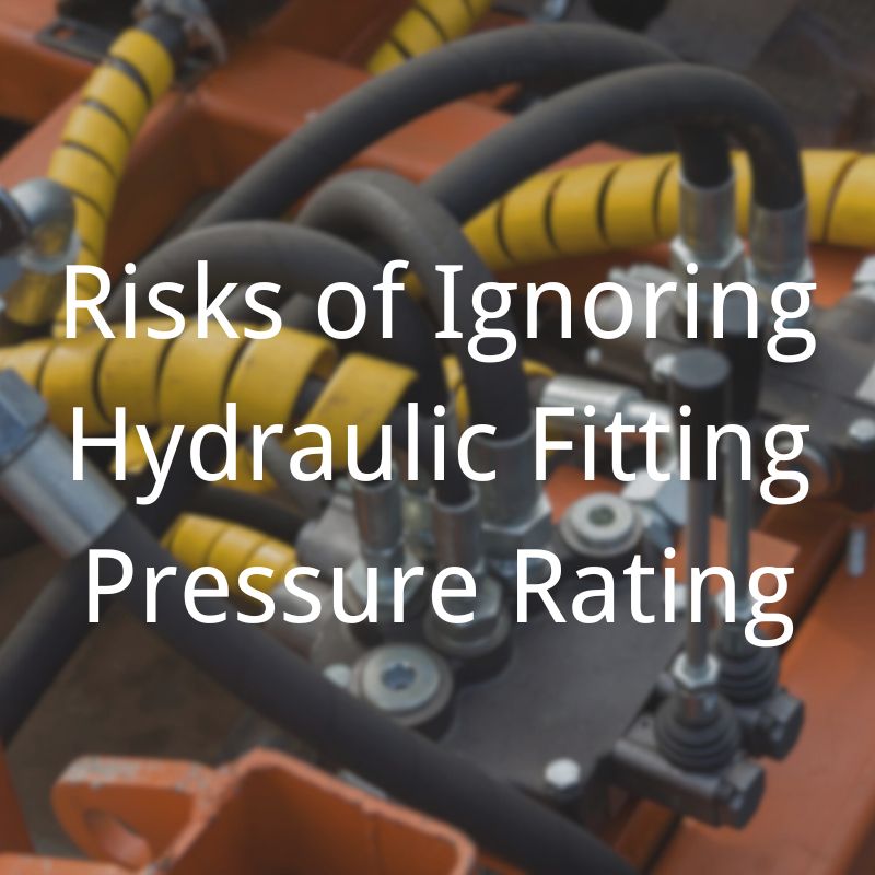
Risks of Ignoring Hydraulic Fitting Pressure Rating
Table of Contents
Introduction
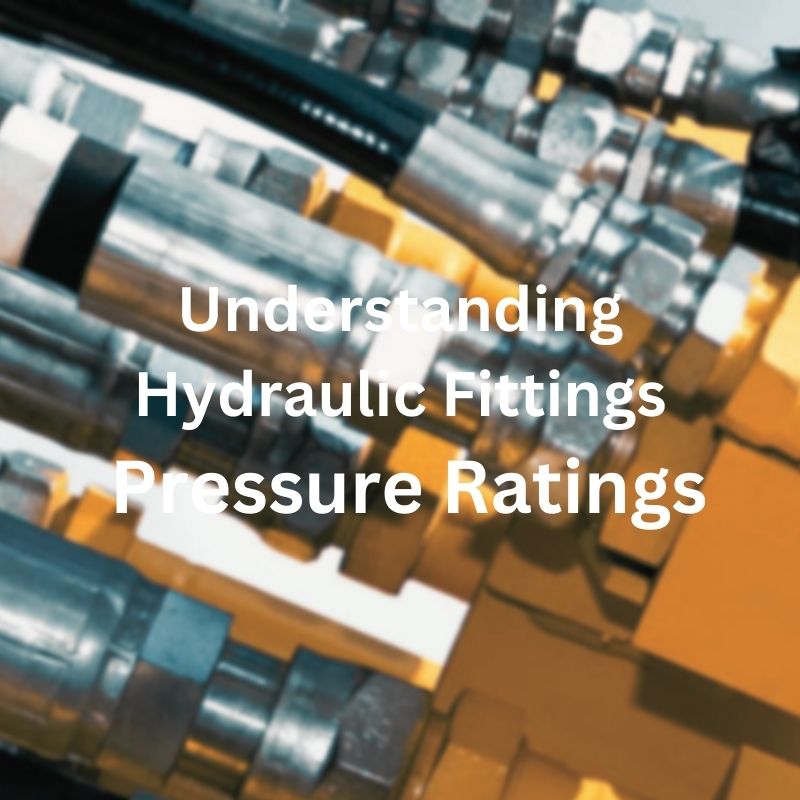
Hydraulic fittings are integral to the function of a hydraulic system; they are the connectors that ensure the seamless flow of hydraulic fluids under pressure. Not only are these components a mechanical necessity, but they also embody the engineering precision needed to safely and efficiently meet the demands of the system. The pressure ratings assigned to hydraulic couplings are not arbitrary numbers, but critical specifications that determine the couplings’ ability to withstand the working pressures of the system. Ignoring these ratings not only jeopardizes the efficiency of the hydraulic system, but also poses a direct threat to safety, resulting in leaks, system failures and catastrophic accidents. Therefore, knowing and adhering to these pressure ratings is critical not only to the performance of your hydraulic system, but also to the safety of its operation.
Understanding Hydraulic Fitting Pressure Ratings
The Essence of Pressure Ratings
Pressure ratings are the cornerstone of hydraulic fitting integrity, serving as the definitive guide for the maximum internal pressure a fitting can handle without failure. These ratings are not arbitrary; they are the culmination of extensive testing and analysis, designed to ensure that every fitting can perform under specified conditions without risk of failure.
The Role of Standards in Pressure Ratings
Society of Automotive Engineers (SAE)
The SAE sets forth rigorous standards for hydraulic fittings, specifying pressure ratings based on the fitting’s design, material, and intended use. These standards ensure consistency and reliability across fittings used in automotive applications, where safety and performance are paramount.
International Organization for Standardization (ISO)
Similarly, the ISO prescribes global standards for hydraulic fittings, encompassing a wide range of pressure ratings to suit various industrial applications. ISO standards are integral to ensuring compatibility and interchangeability of hydraulic fittings worldwide, fostering international cooperation and understanding in hydraulic system design.
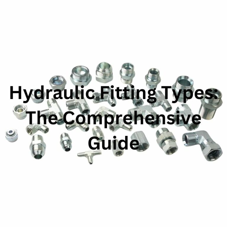
Types of Hydraulic Fittings and Their Pressure Ratings
Flanged Fittings
Flanged fittings are characterized by their high-pressure capabilities, making them ideal for heavy-duty applications. The pressure rating of a flanged fitting depends on its size, material, and the standard it adheres to, ensuring a secure connection in high-pressure environments.
Threaded Fittings
Threaded fittings, common in both industrial and automotive systems, are rated based on the thread design (e.g., NPT, BSPP) and the material’s strength. These fittings offer versatility and ease of installation, with pressure ratings suited to medium- to high-pressure systems.
Barbed Fittings
Barbed fittings, often used in low-pressure applications, have pressure ratings that reflect their design for securing hoses without the need for clamps or crimps. Their ratings are determined by the barb design, material, and hose compatibility, ensuring a leak-free connection at lower pressures.

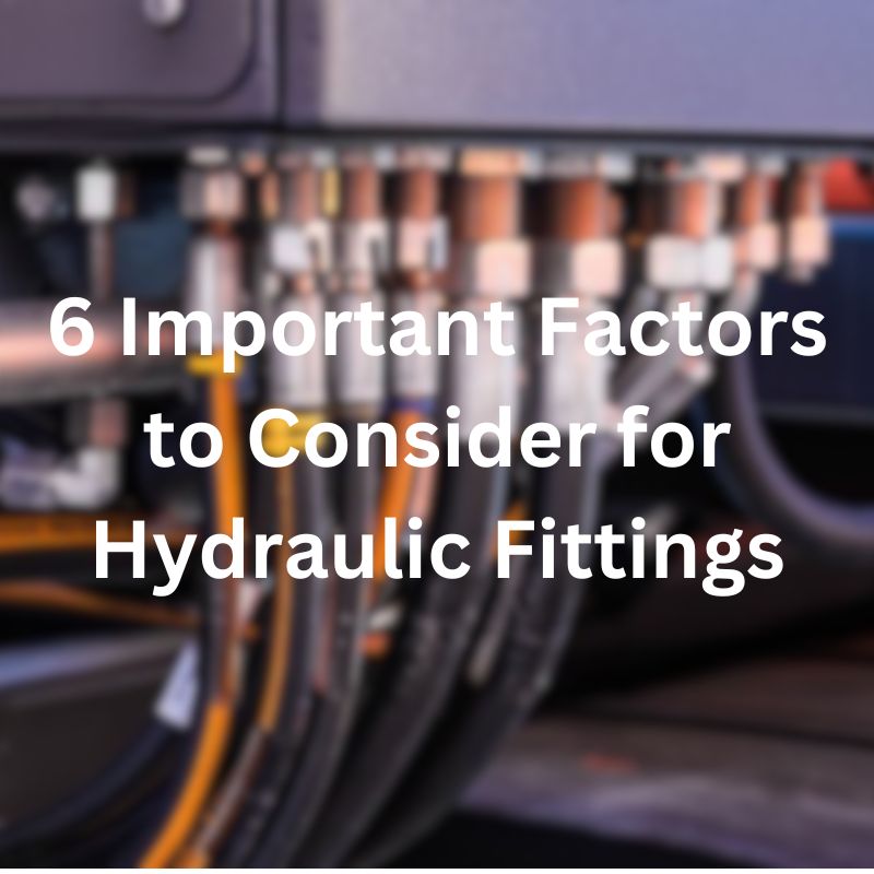
The Importance of Matching Fittings to System Requirements
Selecting hydraulic fittings with appropriate pressure ratings is crucial to system safety and efficiency. A mismatch can lead to leaks, bursts, and system failures, underscoring the importance of understanding and adhering to the rated pressures. Engineers and technicians must evaluate the system’s operational pressure, including any potential surges, to choose fittings that can withstand the system’s maximum pressure demands.
The Science Behind Pressure Ratings
Fundamental Concepts in Calculating Pressure Ratings
The determination of pressure ratings is a sophisticated process that integrates the principles of material science and mechanical engineering. It begins with an understanding of the fitting’s material properties, which include tensile strength, ductility, and resistance to environmental factors. These properties dictate how a material behaves under pressure, influencing its suitability for various hydraulic applications.
The Role of Material Composition

Steel: Known for its high tensile strength and durability, steel is a common choice for hydraulic fittings intended for high-pressure applications. Its robust nature allows it to withstand significant pressure variations, making it ideal for industrial settings.
Stainless Steel: Offers enhanced corrosion resistance compared to regular steel, making it suitable for hydraulic systems exposed to harsh environmental conditions. Stainless steel fittings are preferred in applications where preventing rust and corrosion is critical to maintaining system integrity.
Brass: Exhibits excellent machinability and resistance to corrosion and is typically used in lower-pressure applications. Brass fittings are common in systems where corrosion resistance is more crucial than high pressure handling capacity.
Design Considerations in Pressure Rating Calculations
The design of a hydraulic fitting significantly influences its pressure rating. Factors such as the fitting’s geometry, wall thickness, and the type of sealing mechanism employed are meticulously analyzed. The design must account for the worst-case scenario that the fitting might encounter, including pressure spikes and thermal variations, to ensure reliability under all operational conditions.
Ensuring Uniformity and Reliability
By following the established standards, manufacturers can ensure that their hydraulic fittings meet or exceed the required safety and performance criteria. This uniformity is crucial for system designers and engineers, who rely on accurate pressure ratings to select appropriate fittings for their hydraulic systems.
The Impact of Operating Conditions
The operating conditions, including temperature, fluid type, and pressure fluctuations, play a critical role in the real-world performance of hydraulic fittings. The pressure rating must reflect the fitting’s ability to operate safely under the specific conditions it will encounter. This involves considering the effects of temperature on material properties and the compatibility of the fitting material with the hydraulic fluid.
Risks of Overlooking Pressure Ratings
System Failures
Understanding System Failures
System failures in hydraulic systems can have devastating effects, often culminating from the use of inadequately rated hydraulic fittings. These failures are not mere inconveniences but serious events that compromise the entire system’s integrity and functionality.
Causes of System Failures
- Inadequate Pressure Ratings: Fittings that are not rated for the operational pressures of the system are prone to failure. This mismatch can occur due to oversight, incorrect specifications, or misunderstanding of the system’s pressure requirements.
- Leaks and Bursts: Under pressure, inadequately rated fittings may leak or burst. Leaks can gradually undermine system performance, while bursts can lead to immediate and catastrophic system failure.
Consequences of System Failures
- Operational Downtime: One of the immediate consequences of system failures is operational downtime. This halt in operation affects productivity and can lead to significant financial losses, especially in industrial settings where time is money.
- Damage to Machinery: Leaks and bursts can cause damage to surrounding machinery. The force of a burst fitting, for example, can be enough to damage nearby components, leading to costly repairs or replacements.
- Environmental Contamination: Hydraulic fluid leaks are a potential source of environmental contamination. In outdoor settings or near water bodies, such leaks can have severe ecological impacts, affecting wildlife and water quality.
Safety Hazards
The Gravity of Safety Hazards
Safety hazards associated with hydraulic systems primarily stem from the misuse or oversight of hydraulic fittings’ pressure ratings. When these critical components fail to match the system’s pressure demands, the result can be catastrophic, posing serious threats to workplace safety.
Causes of Safety Hazards
- Mismatched Pressure Ratings: Utilizing fittings that are unsuitable for the system’s pressure levels can lead to mechanical failures that compromise safety.
- Leaks and Explosions: Faulty or inadequate fittings can rupture, causing leaks or explosions. Leaks may seem less severe but can create slippery surfaces, leading to falls and injuries. Explosions, on the other hand, can cause immediate harm to anyone in the vicinity.
Impact on Workplace Safety
- Endangering Lives: The most severe consequence of neglecting fitting pressure ratings is the potential loss of life. Explosions and high-velocity leaks can have fatal outcomes, emphasizing the need for strict compliance with safety standards.
- Creating Unsafe Work Environments: Even when non-fatal, accidents related to hydraulic failures can create environments that are unsafe for workers. The psychological impact of working in an unsafe environment can also not be underestimated, potentially leading to reduced productivity and morale.
Mitigation Strategies
- Compliance with Standards: Rigorous adherence to pressure rating standards, such as those set by SAE and ISO, is non-negotiable. These standards are designed to ensure that fittings can safely contain the system’s operational pressures.
- Education and Training: Educating personnel on the importance of pressure ratings and training them to recognize and address potential issues can significantly reduce safety hazards. Awareness can empower workers to take proactive measures to ensure their safety and that of their colleagues.
- Regular Safety Audits: Implementing regular safety audits of hydraulic systems can help identify risks before they manifest as accidents. These audits should assess the suitability of all system components, including hydraulic fittings, and ensure they meet the required safety standards.
Operational Efficiency
- Reduced System Performance: Even if outright failures do not occur, using fittings that are not rated appropriately for the system’s pressure can lead to reduced efficiency and performance. This can affect the overall output and quality of operations.
- Increased Maintenance Needs: Systems that are not optimized with correctly rated fittings may require more frequent maintenance, adding to operational costs and reducing the time equipment is available for productive use.
Financial Impacts
Ignoring the pressure ratings of hydraulic fittings can lead to significant financial repercussions for businesses. Here are some additional considerations:
- Repair and Replacement Costs: Following a system failure, the cost of repairing or replacing damaged components can be substantial. This is not limited to the fittings themselves but can extend to any part of the system compromised by the failure.
- Lost Revenue: Downtime due to system failures means lost production time. For industries where operations are continuous or time-sensitive, this can translate into significant lost revenue.
- Legal and Compliance Costs: There may be legal ramifications if a failure leads to environmental damage or personal injury. The costs associated with fines, legal proceedings, and settlements can be considerable.
- Insurance Premiums: Companies with a history of hydraulic system failures may face higher insurance premiums. Insurers may view them as high-risk clients due to a track record of accidents and failures.
Practices for Ensuring Correct Pressure Rating
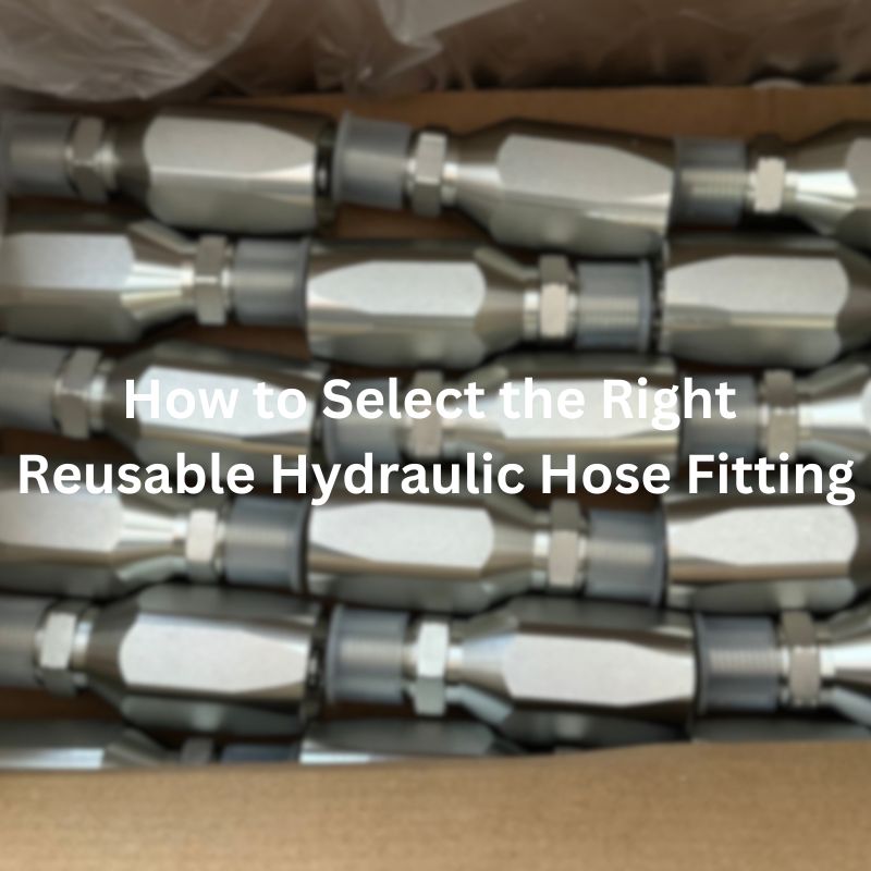
Selecting the Right Hydraulic Fittings
Ensuring the safety and efficiency of hydraulic systems begins with the selection of appropriate hydraulic fittings. This critical process involves several key steps:
- Understand Pressure Rating Standards: Familiarize yourself with the relevant standards, such as those set by SAE and ISO, which define pressure ratings for hydraulic fittings. These standards ensure that the fittings are capable of withstanding the operational pressures of your hydraulic system.
- Interpret Specifications Accurately: Learn to read and interpret the specifications of hydraulic fittings correctly. This includes understanding the pressure ratings, material composition, and any other critical parameter that might affect the fitting’s performance under pressure.
- Ensure Compatibility: Match the fitting’s pressure rating with the maximum operating pressure of the system, including considerations for pressure spikes. Compatibility also extends to the type of fluid used in the system, as some materials are better suited for certain fluids than others.
- Consult Experts When Necessary: When in doubt, consult with hydraulic system experts or the fitting manufacturers. Their expertise can guide you in selecting the most appropriate fittings for your specific application.
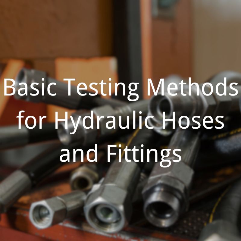
Regular System Inspection and Maintenance
Maintaining the integrity of a hydraulic system requires diligent inspection and maintenance, focusing on ensuring that all components, especially the fittings, comply with their designated pressure ratings.
- Routine Inspection: Conduct regular inspections of hydraulic fittings for signs of wear, corrosion, or damage. This includes checking for leaks, which can be indicative of a fitting not holding up to its rated pressure.
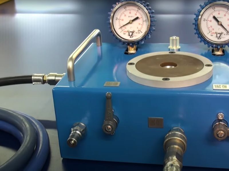
- Pressure Testing: Periodically perform pressure tests to verify that fittings can handle the system’s operational pressure. This practice helps identify weak points in the system before they lead to failure.
- System Audits: Regular system audits allow for a comprehensive review of the hydraulic system’s health, including the adequacy of fitting pressure ratings. Audits can pinpoint areas needing improvement or replacement to maintain system integrity.
Conclusion
In summary, efforts to apply knowledge of pressure ratings and a commitment to continually learning and adapting to technological advances are critical. These efforts not only protect valuable human and material resources, but also contribute to the overall goal of sustainable and reliable operation of hydraulic systems. As we move forward, the collective expertise and vigilance of industry professionals will continue to be the foundation for safe and efficient hydraulic system design and maintenance.


