Have you ever faced downtime or equipment failure because of an incompatible hydraulic quick coupler? Identifying the right hydraulic quick coupler is crucial for the seamless operation of your hydraulic systems, preventing costly interruptions and ensuring safety. Hydraulic quick couplers are essential components in hydraulic systems, allowing for quick and efficient connections and disconnections of fluid lines. This post aims to provide a comprehensive guide on how to correctly identify hydraulic quick couplers. Accurate identification not only enhances system performance but also ensures compatibility and safety, reducing the risk of leaks, equipment damage, and operational inefficiencies.
Hydraulic quick couplers are specialized connectors used in hydraulic systems to facilitate the quick and easy connection and disconnection of hydraulic lines. These couplers are designed to prevent fluid leakage and contamination during the connection process, ensuring a secure and efficient transfer of hydraulic fluid. Quick couplers are commonly used in a variety of industries, including construction, agriculture, and manufacturing, where they help to enhance operational efficiency by reducing downtime associated with connecting and disconnecting hydraulic equipment.
ISO A and B quick couplers are standardized couplers that adhere to specific international standards set by the International Organization for Standardization (ISO). These couplers are widely used due to their compatibility with equipment from different manufacturers. ISO A couplers feature a ball valve design, which provides a reliable seal and is suitable for general hydraulic applications. ISO B couplers, on the other hand, use a poppet valve design, offering a higher flow capacity and better performance in high-pressure applications.
Flat face couplers are designed with a flat sealing surface, which minimizes fluid loss and reduces the risk of contamination during connection and disconnection. These couplers are particularly well-suited for applications where cleanliness is critical, such as in construction and agricultural equipment. The flat face design also makes them easier to clean, further enhancing their suitability for environments where maintaining hydraulic fluid purity is essential.
High flow couplers are engineered to provide a higher flow rate compared to standard quick couplers, making them ideal for applications requiring a significant volume of hydraulic fluid transfer. These couplers are commonly used in heavy machinery and equipment that demands high flow capacity to operate efficiently. The design of high flow couplers typically includes larger internal passageways to accommodate increased fluid flow while maintaining a secure and leak-free connection.

Screw-to-connect couplers are designed with a threaded connection mechanism, providing a robust and secure connection that can withstand high pressure and severe mechanical stresses. These couplers are ideal for applications involving high vibration or where accidental disconnection could lead to significant operational hazards. The screw-to-connect design ensures that the couplers remain securely fastened, even under challenging conditions, making them suitable for heavy-duty industrial applications.
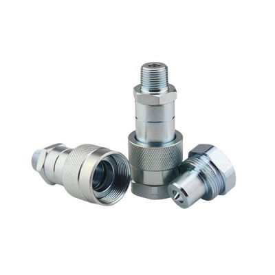
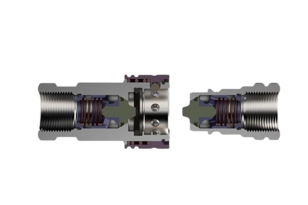
Hydraulic quick couplers consist of two main parts: the female half and the male half. The female half typically includes a locking mechanism that securely holds the male half in place when connected. The male half features a protruding end that fits into the female half, creating a secure and leak-free connection. Both halves are designed to align perfectly, ensuring a tight seal and efficient fluid transfer.
Seals and O-rings are critical components of hydraulic quick couplers, providing a reliable seal that prevents hydraulic fluid from leaking during operation. These components are typically made from high-quality materials such as nitrile, Viton, or polyurethane, chosen for their resistance to hydraulic fluids and their ability to maintain a tight seal under high pressure. Proper maintenance and regular replacement of seals and O-rings are essential to ensure the longevity and performance of the couplers.
Valves within hydraulic quick couplers control the flow of hydraulic fluid. Different types of valves, such as ball valves and poppet valves, are used depending on the specific application requirements. Ball valves provide a reliable and simple mechanism for fluid control, while poppet valves offer higher flow capacity and better sealing performance under high-pressure conditions. The choice of valve type depends on factors such as flow rate, pressure, and the need for contamination control.

Dust caps are protective covers used to shield the connection points of hydraulic quick couplers from dirt, debris, and contaminants when the couplers are not in use. These caps are essential for maintaining the cleanliness and integrity of the hydraulic system, preventing foreign particles from entering the fluid lines and causing damage or reduced performance. Dust caps are typically made from durable materials like plastic or rubber and are designed to fit securely over the coupler ends.
Hydraulic quick couplers come in various shapes and designs, each tailored to specific applications and performance requirements. Understanding the different shapes and designs is crucial for correct identification and application.
ISO A and B Couplers: These typically have a cylindrical shape with distinct locking mechanisms that are easy to identify by their uniform structure. ISO A couplers usually feature a ball valve, whereas ISO B couplers often have a poppet valve design.
Flat Face Couplers: These are characterized by their flat, smooth sealing surface, which distinguishes them from other couplers. The flat face design minimizes fluid loss and contamination, making them easily recognizable.
High Flow Couplers: Often larger in size to accommodate higher flow rates, these couplers can be identified by their broader internal passageways and robust build.
Screw-to-Connect Couplers: These have a threaded connection mechanism, which is a key visual feature. The presence of external threads on the male half and corresponding internal threads on the female half make them stand out.
Color coding is a practical method for quickly identifying the type and application of hydraulic quick couplers. Manufacturers often use specific colors to denote different series, pressure ratings, or fluid compatibility.
Series Identification: Some manufacturers use distinct colors to differentiate between various series of couplers. For instance, ISO A might be color-coded differently than ISO B.
Pressure Ratings: Different pressure ratings can be indicated by color. For example, low-pressure couplers might be blue, while high-pressure ones could be red.
Fluid Compatibility: Colors can also signify compatibility with specific hydraulic fluids. Green might indicate compatibility with bio-degradable fluids, while yellow could denote compatibility with standard hydraulic oils.
Markings and labels on hydraulic quick couplers provide essential information about their specifications and compatibility. Understanding these markings can aid in proper identification and application.
Manufacturer Logos
Most hydraulic quick couplers will have the manufacturer’s logo etched or stamped on the body. This logo not only identifies the brand but often provides a reference for quality and compatibility with other components from the same manufacturer.
Size and Pressure Ratings
Size Markings: Couplers typically have size markings that indicate the diameter of the connection points. These markings are crucial for ensuring that the coupler fits the corresponding hydraulic lines or ports.
Pressure Ratings: Pressure ratings are usually marked on the coupler to denote the maximum operating pressure. This information is vital to prevent overloading the coupler, which could lead to failure or safety hazards. The ratings are often indicated in PSI (pounds per square inch) or bar.
Diameter
The diameter of a hydraulic quick coupler is one of the primary specifications used to ensure compatibility with hydraulic systems. It is measured across the coupling’s mating end and is crucial for matching the coupler to the hydraulic hoses and ports. Common diameters include 1/4″, 3/8″, 1/2″, and 3/4″, but many other sizes are available to suit specific applications.
Length
The overall length of a hydraulic quick coupler affects how it fits within a hydraulic system, especially in confined spaces. This dimension is measured from the end of the male half to the end of the female half when connected. The length can vary significantly between different types of couplers and should be considered when designing or modifying hydraulic systems.
Steel
Steel is a common material for hydraulic quick couplers due to its strength and durability. It is suitable for high-pressure applications and environments where mechanical strength is crucial. Steel couplers are often plated with zinc or other coatings to enhance corrosion resistance.
Brass
Brass is used for its excellent corrosion resistance and moderate strength. It is ideal for lower-pressure applications and environments where exposure to water or corrosive fluids is a concern. Brass couplers are commonly found in agricultural and industrial settings.
Stainless Steel
Stainless steel offers superior corrosion resistance and strength, making it suitable for high-pressure and high-corrosion environments, such as marine and chemical processing industries. Stainless steel couplers are also preferred in applications where hygiene is essential, like in food processing.
Maximum Operating Pressure
The maximum operating pressure indicates the highest pressure at which the coupler can safely function during regular use. This specification ensures that the coupler can handle the pressures exerted by the hydraulic system without risk of failure. It is typically measured in PSI (pounds per square inch) or bar. For example, a standard hydraulic quick coupler might have a maximum operating pressure of 5,000 PSI (345 bar).
Burst Pressure
Burst pressure is the pressure at which the coupler will fail catastrophically. This rating is significantly higher than the maximum operating pressure and provides a safety margin to prevent failure under extreme conditions. Burst pressure is a critical specification for ensuring the overall safety and reliability of hydraulic systems. For example, a coupler with a maximum operating pressure of 5,000 PSI might have a burst pressure of 20,000 PSI (1,380 bar).
Push-to-Connect Mechanism
Description: Push-to-connect couplers are designed for quick and easy connections. Simply pushing the male half into the female half engages the coupler, which is secured by internal locking mechanisms.
Advantages: Fast connection and disconnection without the need for tools, ideal for applications requiring frequent coupling and uncoupling.
Applications: Commonly used in agricultural, construction, and industrial equipment where speed and ease of use are critical.
Screw-to-Connect Mechanism
Description: Screw-to-connect couplers require the male half to be screwed into the female half, creating a robust and secure connection. The threaded mechanism ensures a tight seal even under high pressure and vibration.
Advantages: Provides a more secure and reliable connection, suitable for high-pressure applications and environments with significant vibration or mechanical stress.
Applications: Ideal for heavy-duty industrial applications, including construction machinery, mining equipment, and hydraulic presses.

Ball Valve
Description: Ball valves use a spherical ball with a hole through the center that controls fluid flow. When the valve is open, the hole aligns with the flow path; when closed, the ball rotates to block the flow.
Advantages: Simple and reliable, offering quick operation and good sealing properties.
Applications: Suitable for a wide range of hydraulic systems, including those requiring frequent operation and minimal fluid leakage.
Poppet Valve
Description: Poppet valves use a poppet (a movable seal) that moves perpendicularly to the flow direction to open and close the flow path. The poppet is spring-loaded to ensure a tight seal when closed.
Advantages: Provides a higher flow rate and better sealing under high-pressure conditions compared to ball valves.
Applications: Commonly used in high-pressure applications and where minimal fluid loss and contamination are critical.
Flat Valve
Description: Flat valves, often found in flat-face couplers, have a flat sealing surface that minimizes fluid loss and contamination. The flat design makes them easy to clean and reduces the chance of dirt entering the hydraulic system.
Advantages: Excellent contamination control and minimal fluid loss during connection and disconnection.
Applications: Ideal for applications in construction, agriculture, and environments where cleanliness is paramount.
How to Identify Based on Flow Rate Specifications
Description: Flow rate is the volume of fluid that passes through the coupler per unit of time, typically measured in gallons per minute (GPM) or liters per minute (LPM).
Identification: Manufacturers provide flow rate specifications for their couplers, which can be found in product datasheets or markings on the coupler itself. These specifications ensure that the coupler can handle the required flow rate without causing significant pressure drops or system inefficiencies.
Importance: Selecting a coupler with the appropriate flow rate is crucial to maintaining system performance and preventing issues such as cavitation or excessive pressure loss.
ISO Standards
Description: The International Organization for Standardization (ISO) sets global standards for hydraulic quick couplers, ensuring compatibility and interchangeability between different manufacturers and systems. Common ISO standards include ISO 7241-1 series A and B.
Advantages: Ensures that couplers from different manufacturers can be used interchangeably, providing flexibility and convenience in sourcing and replacing components.
SAE Standards
Description: The Society of Automotive Engineers (SAE) sets standards for hydraulic couplers, particularly in the automotive and aerospace industries. SAE standards ensure that couplers meet specific performance and safety criteria.
Advantages: Assures quality and performance, particularly in high-stress and high-reliability applications.
In this post, we explored the intricacies of identifying hydraulic quick couplers, covering their types, components, technical specifications, and functional identification methods. Proper identification is crucial for ensuring system compatibility, performance, and safety. By applying the tips and best practices outlined, you can enhance the efficiency and reliability of your hydraulic systems. We encourage you to share this valuable information with colleagues who may benefit, helping to spread knowledge and improve operational practices across the industry.
Hydraulic quick couplers are connectors used in hydraulic systems to allow for the quick and easy connection and disconnection of hydraulic lines. They are important because they prevent fluid leakage and contamination, ensuring efficient and safe operation of hydraulic systems.
To determine the correct type, consider the specific requirements of your application, such as the operating pressure, flow rate, and the type of hydraulic fluid used. Additionally, check the compatibility with your existing hydraulic system and refer to manufacturer datasheets and standards like ISO and SAE.
Push-to-connect couplers allow for quick and tool-free connection and disconnection by simply pushing the male half into the female half. Screw-to-connect couplers require the male half to be screwed into the female half, providing a more secure and robust connection suitable for high-pressure and high-vibration environments.
Color coding is used to quickly identify the type and specifications of hydraulic quick couplers, such as series, pressure ratings, or fluid compatibility. This helps in selecting the right coupler and avoiding potential mismatches and operational issues.
The pressure rating of a hydraulic quick coupler is usually marked on the body of the coupler. It can also be found in the product datasheet provided by the manufacturer. The rating is typically indicated in PSI (pounds per square inch) or bar, showing the maximum operating pressure and burst pressure.
Common materials include steel, brass, stainless steel, and aluminum. Choose the material based on your application needs: steel for high strength and durability, brass for corrosion resistance in moderate pressure environments, stainless steel for high corrosion resistance and strength, and aluminum for lightweight applications.