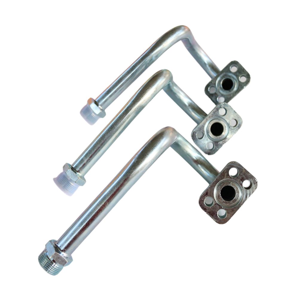
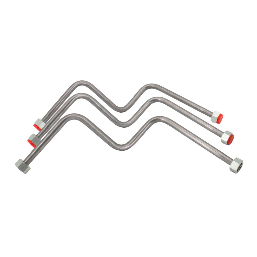
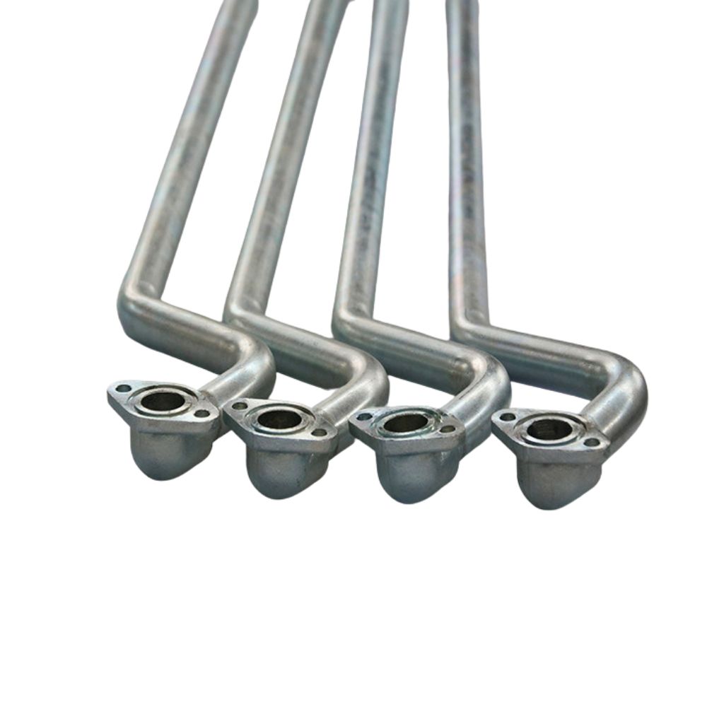
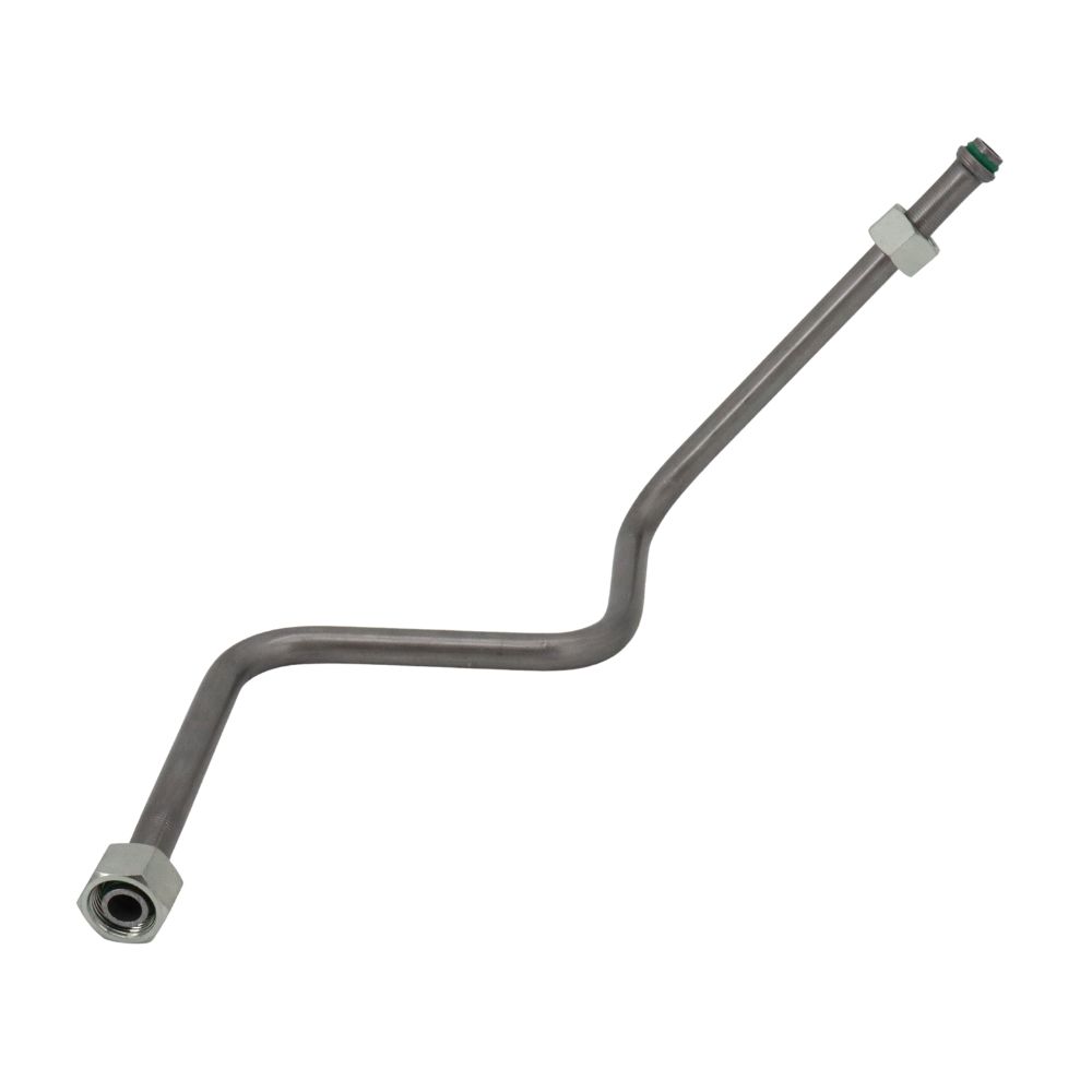
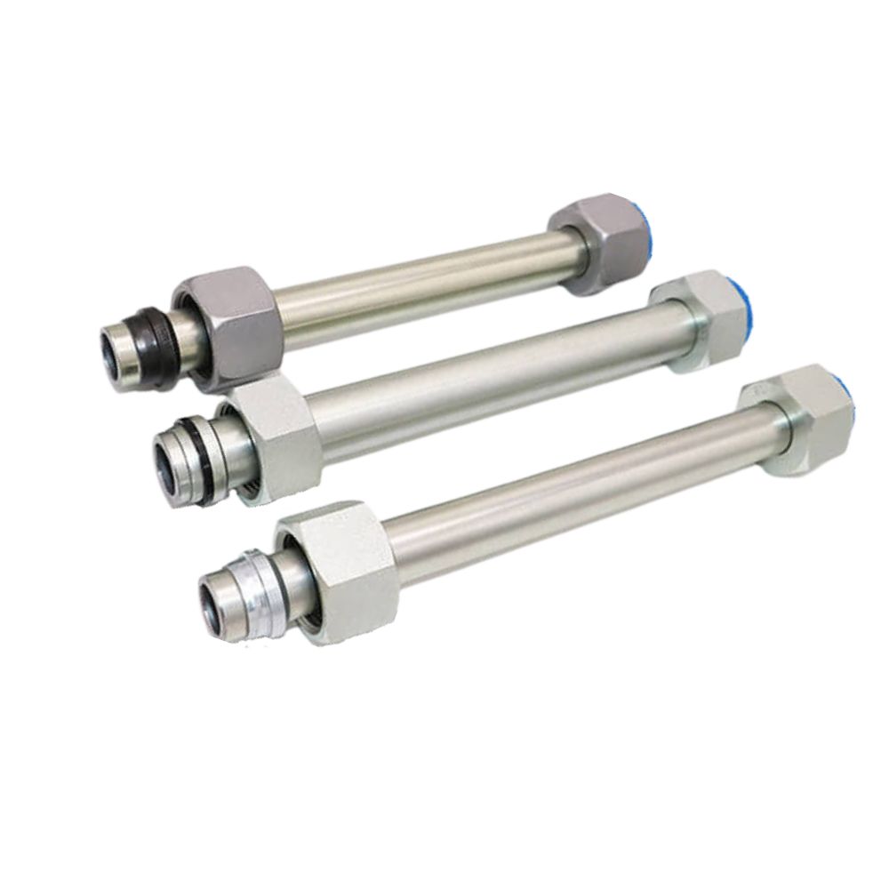
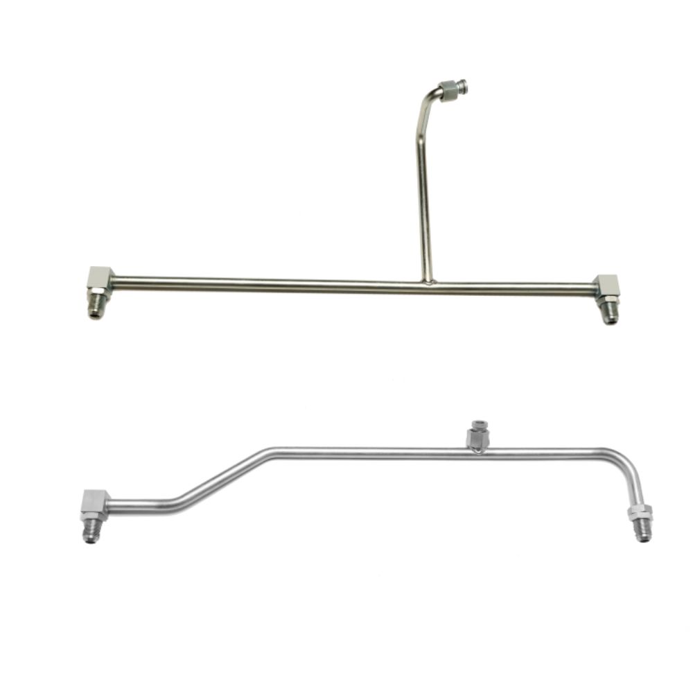
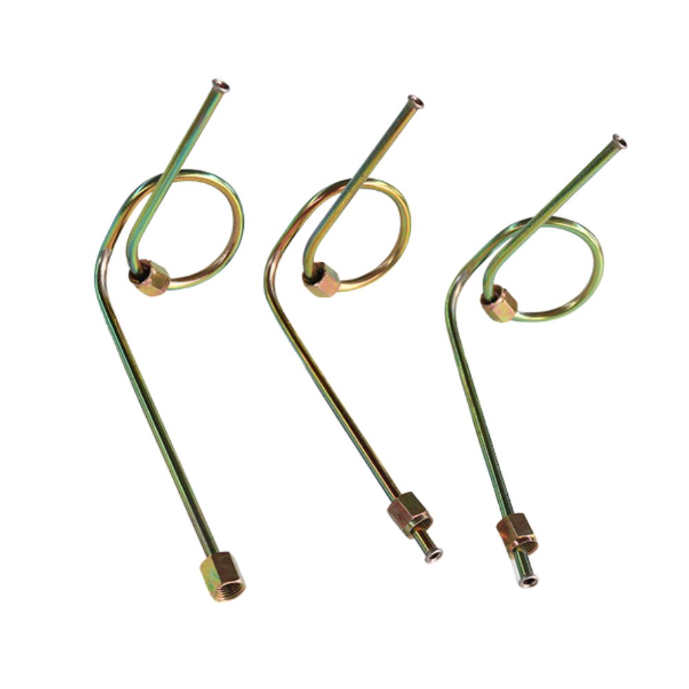
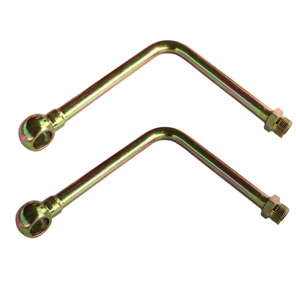
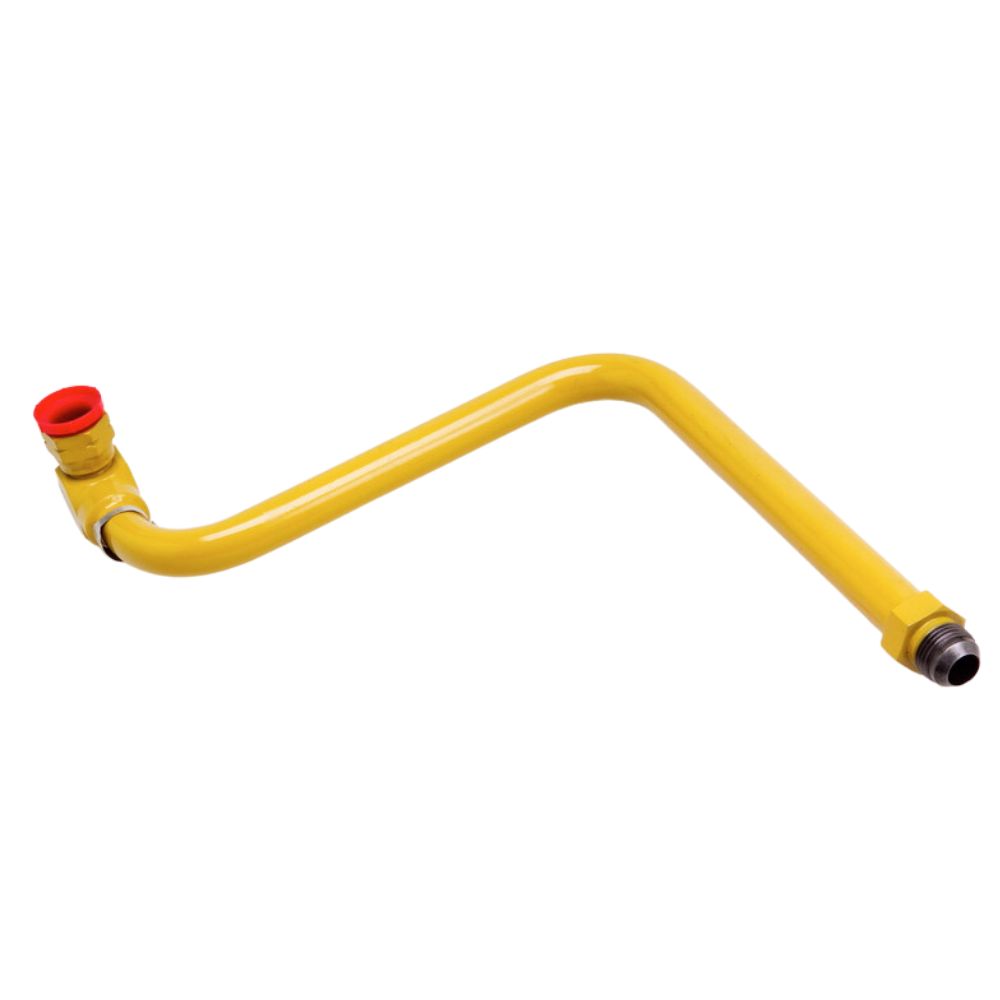
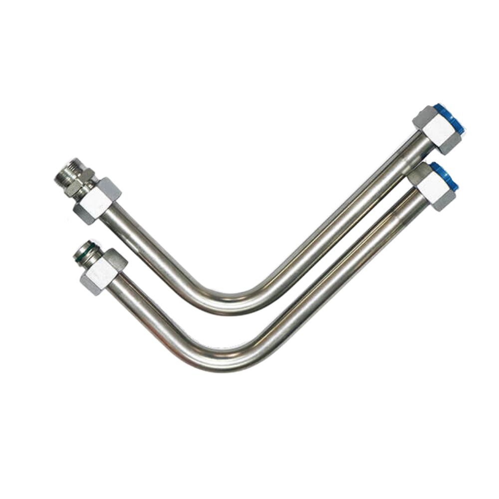
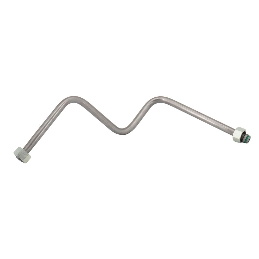
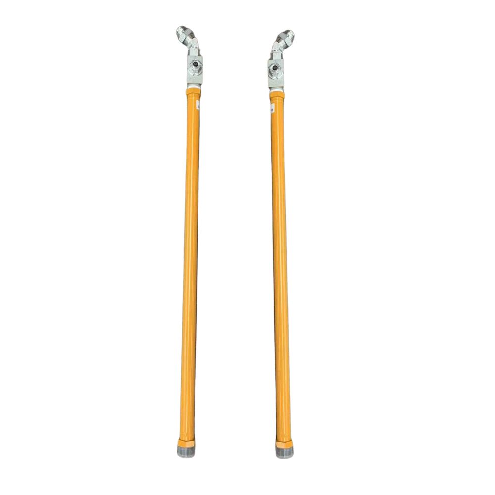
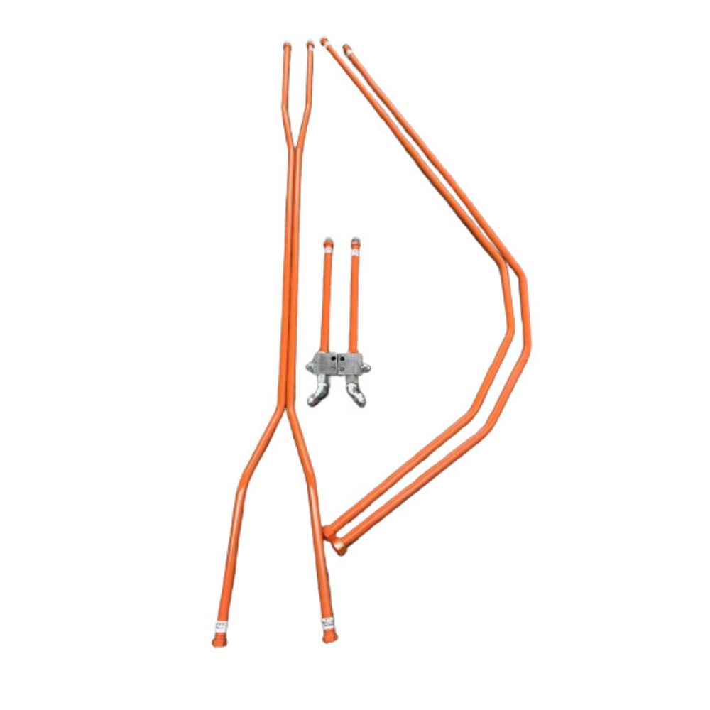
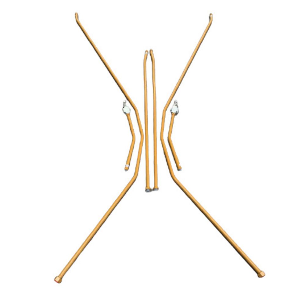
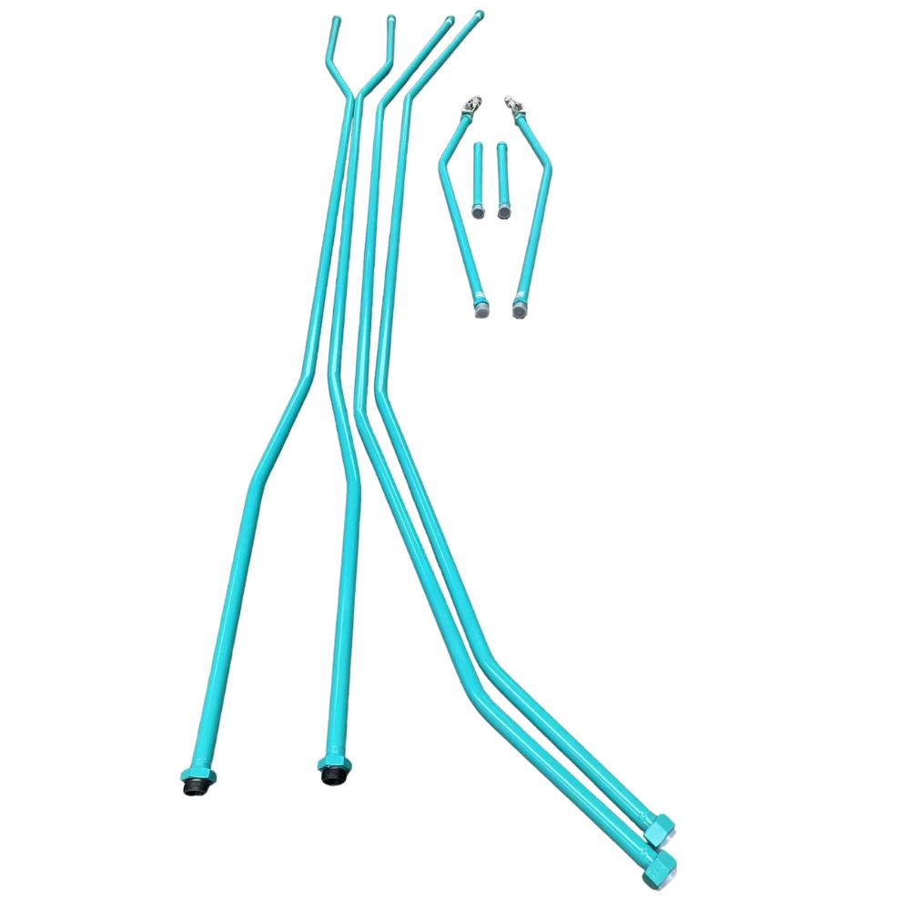
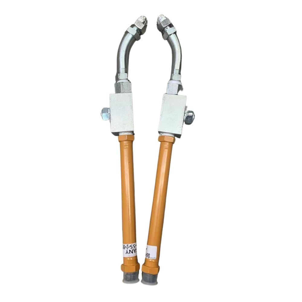
Longitudinal tube cracks are fissures that run parallel to the length of a tube, often resulting from stress, fatigue, or manufacturing defects. These cracks can lead to catastrophic failures if not identified and addressed promptly. The implications of tube cracks extend beyond immediate fluid leaks; they can cause system malfunctions, increase maintenance costs, and pose serious safety risks to operators and equipment.
Understanding Longitudinal Tube Cracks
A. Definition of Longitudinal Tube Crack
Tube cracks are defined as linear fissures that occur along the length of a tube, typically parallel to its axis. These cracks can vary in size and depth, often appearing as narrow lines on the surface of the tube. Their formation is primarily linked to mechanical stresses, fatigue, and material defects. Unlike transverse cracks, which cross the diameter of the tube, longitudinal cracks extend the entire length, posing unique challenges for detection and repair.
B. Visual Representation and Common Locations of These Cracks
Visual representation of tube cracks is crucial for understanding their formation and potential impact. These cracks often manifest as fine lines or fractures on the tube surface and may not always be immediately visible to the naked eye. Common locations for longitudinal cracks include:
Welded Seams: Areas where tubes are joined together, particularly if low-quality welding techniques were employed.
Bend Points: Sections of the tube that experience high levels of stress during bending operations.
High-Pressure Zones: Areas subjected to elevated pressure fluctuations, where the material may exceed its fatigue limit.
C. The Role of Hydraulic Tubes in Fluid Systems
Hydraulic tubes play a critical role in fluid systems by facilitating the movement of hydraulic fluids under pressure. They serve as the primary pathway for transmitting energy, ensuring that hydraulic machinery operates smoothly and efficiently. Key functions of hydraulic tubes include:
Pressure Resistance: Tubes must withstand high pressures without failure, making material selection and design crucial.
Fluid Transport: Ensuring a continuous flow of hydraulic fluid is essential for system functionality and performance.
Safety Considerations: Properly maintained tubes prevent leaks and system failures, safeguarding both equipment and personnel.
Common Causes of Tube Cracks
A. Poor Quality Welded Tubes
Explanation of Welding Processes
Welding is a critical process in the manufacturing of hydraulic tubes, especially in the production of welded tubes. Various welding techniques are employed, including Metal Inert Gas (MIG), Tungsten Inert Gas (TIG), and submerged arc welding. Each of these methods has specific advantages, influencing the overall quality of the weld. For instance, MIG welding is often faster and more versatile, making it suitable for various materials. In contrast, TIG welding provides greater control over the heat input, which is beneficial for thinner materials or those requiring precise welding.
The quality of the weld plays a crucial role in the structural integrity of hydraulic tubes. Poor welding practices can result in weak joints that are prone to cracking, particularly under the stress of hydraulic pressures. Factors such as welding speed, heat settings, and filler material can all impact the quality of the weld, making it imperative to adhere to established welding standards and practices.
Identification of Poor Weld Quality Indicators
Poor-quality welds can be a significant source of tube cracks. Several indicators can help identify these issues:
Visible Weld Seams: A pronounced or uneven weld seam may indicate poor fusion between the base metal and the filler material, increasing the likelihood of structural failure over time.
Inconsistent Weld Penetration: Uneven penetration can lead to weak spots in the weld that are more susceptible to stress concentrations, which may ultimately result in cracks.
Surface Imperfections: Issues such as craters, porosity, and slag inclusions can compromise the weld’s structural integrity. These imperfections create stress risers where cracks are more likely to initiate.
Regular inspection and adherence to quality standards, such as SAE J525, can help mitigate these issues. Employing advanced inspection techniques can further enhance the detection of poor weld quality before the tubes are put into service.
B. Excessive Cyclic Pressure
Definition of Cyclic Pressure and Its Effects
Cyclic pressure refers to the fluctuations in pressure that hydraulic systems experience during operation. These variations may arise from changes in load, fluid dynamics, or other operational conditions. Over time, these repeated pressure cycles can cause fatigue in the material, leading to cracks.
The phenomenon of cyclic fatigue is a crucial consideration in hydraulic system design. When materials are subjected to repeated loading and unloading cycles, they can develop microscopic cracks that grow progressively until they reach a critical size, resulting in catastrophic failure.
Factors Contributing to Cyclic Pressure in Hydraulic Systems
Several factors can contribute to excessive cyclic pressure:
System Design: Poorly designed hydraulic systems may expose tubes to unnecessary pressure variations, making them more vulnerable to fatigue. Engineers need to consider all potential pressure fluctuations during the design phase to minimize these risks.
Load Changes: Rapid changes in load can cause abrupt pressure spikes, placing additional stress on the tubes. This situation is especially common in dynamic systems where loads fluctuate frequently, such as in construction equipment or automotive applications.
Pump Performance: Inefficient or malfunctioning pumps can lead to irregular pressure outputs, exacerbating the effects of cyclic pressure. If pumps do not maintain consistent flow rates, they can create pressure surges that put extra stress on the tubing.
Addressing these factors through careful design, regular maintenance, and performance monitoring is vital to mitigating the risks associated with excessive cyclic pressure.
C. Incorrect Tube Wall Selection
Importance of Selecting Appropriate Wall Thickness
The wall thickness of hydraulic tubes is crucial for their performance and longevity. Thicker walls provide better resistance to internal pressures and external forces, thereby enhancing the tube’s ability to withstand operational stresses. It is essential to consider both the maximum working pressure and any potential pressure spikes when selecting wall thickness.
Material selection is equally important; different materials can withstand varying pressures and temperatures. Engineers must evaluate the specific requirements of their application to ensure that the chosen material and wall thickness will provide adequate support.
Consequences of Using Tubes with Insufficient Thickness
Using tubes with inadequate wall thickness can lead to several issues:
Increased Risk of Failure: Thinner walls are less capable of withstanding operational pressures, leading to premature cracks that can jeopardize the entire hydraulic system.
Deformation: Under high pressure, thin-walled tubes are more susceptible to deformation. This distortion can create stress concentrations that initiate cracks, particularly in high-load areas.
Reduced Safety Margin: A lack of appropriate wall thickness reduces the safety factors inherent in hydraulic system design. This decrease in margin increases the likelihood of catastrophic failure, which can result in costly repairs and downtime.
To avoid these pitfalls, engineers should rigorously evaluate their material choices and ensure that they are selecting tubes with appropriate wall thicknesses for their specific applications.
D. Environmental Factors
Impact of Temperature Fluctuations
Temperature variations can significantly affect the integrity of hydraulic tubes. High temperatures can lead to thermal expansion, causing materials to expand and potentially lose their shape. Conversely, low temperatures may lead to contraction, creating stress concentrations that can initiate cracks. Materials can also become more brittle at lower temperatures, further increasing their susceptibility to cracking.
In extreme environments, such as those involving significant temperature variations, selecting materials that can withstand these changes is critical. Manufacturers should consider thermal expansion coefficients when designing hydraulic systems to minimize the risk of cracks related to temperature fluctuations.
Influence of Pressure Spikes on Tube Integrity
Sudden pressure spikes can occur due to various reasons, such as valve closures, pump malfunctions, or flaws in system design. These spikes exert extreme forces on the tube walls, which can exceed the material’s fatigue limit. Consistent monitoring of pressure levels, along with the implementation of pressure relief systems, can help mitigate these risks.
To prevent damage from pressure spikes, hydraulic systems should be equipped with appropriate safety features, such as pressure relief valves and surge suppressors. Regular maintenance and performance assessments can also help identify potential vulnerabilities that may arise from environmental factors.
Symptoms and Detection of Tube Cracks
A. Visual Signs of Longitudinal Cracks
Surface Cracking
Longitudinal cracks may manifest as visible lines or fissures along the length of the tube. These cracks often appear on the exterior surface and can vary in size from small hairline fractures to more pronounced openings. Operators should be vigilant for any signs of discoloration or surface irregularities that could indicate underlying issues.
Deformation of the Tube
Tubes exhibiting longitudinal cracks may also show signs of deformation, such as bulging or changes in diameter. This physical alteration can be indicative of internal stresses that compromise the tube’s integrity.
Fluid Leaks
The presence of fluid leaks near joints or connections can signal longitudinal cracks. Even minor leaks should be thoroughly investigated, as they may point to larger issues within the hydraulic system.
B. Methods for Detecting Cracks
Visual Inspection
Regular visual inspections are essential for the early detection of longitudinal cracks. Technicians should examine the entire length of the tube, paying close attention to weld seams and areas subject to stress.
Non-Destructive Testing (NDT)
Various NDT methods can be employed to detect cracks without damaging the tube. Common techniques include:
Ultrasonic Testing (UT): This method uses high-frequency sound waves to identify imperfections within the material. It is effective for detecting subsurface cracks.
Magnetic Particle Inspection (MPI): Suitable for ferromagnetic materials, MPI reveals surface and near-surface cracks by applying magnetic fields and observing particle accumulation.
Dye Penetrant Testing (DPT): A dye is applied to the surface of the tube, and after a set period, the excess dye is removed. Cracks will retain the dye, allowing for easy identification.
Pressure Testing
Conducting pressure tests can help identify weak points in the system. By gradually increasing the pressure and monitoring for leaks or abnormal readings, operators can pinpoint areas at risk of failure.
C. Importance of Regular Inspection and Maintenance
Preventive Maintenance
Regular inspections and maintenance are vital for the longevity of hydraulic systems. By proactively identifying and addressing potential issues, operators can prevent costly repairs and ensure system reliability.
Safety Assurance
Ensuring the integrity of hydraulic tubes is critical for the safety of operators and equipment. Longitudinal cracks can lead to catastrophic failures, posing risks of injury or damage. Regular monitoring helps mitigate these hazards.
Cost-Effectiveness
Investing in routine inspections can save money in the long run. Early detection of longitudinal cracks allows for timely repairs, reducing the risk of extensive damage that would require more significant resources and downtime.
Preventive Measures
A. Selecting High-Quality Tubes
Recommendations for Material Standards
Choosing high-quality tubes is paramount for ensuring the longevity and reliability of hydraulic systems. Material standards such as SAE J525 and SAE J524 provide guidelines for the manufacturing and testing of hydraulic tubing, ensuring they meet specific performance criteria. These standards cover aspects such as material composition, mechanical properties, and allowable tolerances.
Material Composition: It is essential to select tubes made from materials that can withstand the operational conditions of the hydraulic system. For instance, carbon steel or stainless steel are often preferred due to their strength and resistance to corrosion.
Mechanical Properties: Ensuring that the tube materials have adequate tensile strength, yield strength, and fatigue resistance is crucial. Compliance with industry standards ensures that tubes can handle the stresses associated with hydraulic applications.
Allowable Tolerances: Adhering to specified tolerances for dimensions and wall thickness is vital. Tubes that deviate from these tolerances may not perform as expected under pressure, leading to potential failures.
Benefits of Seamless Tubes versus Welded Tubes
The choice between seamless and welded tubes can significantly impact the performance of hydraulic systems:
Structural Integrity: Seamless tubes, which are produced without welds, offer superior structural integrity and are less prone to failure due to their uniform wall thickness. The absence of a weld seam minimizes stress concentration points, which are common sources of failure in welded tubes.
Pressure Rating: Seamless tubes generally have higher pressure ratings compared to welded tubes. This makes them more suitable for high-pressure applications, providing a safer option in demanding environments.
Manufacturing Variability: Welded tubes can exhibit variability in quality depending on the welding process and technique used. Seamless tubes, on the other hand, are manufactured in a continuous process that reduces the potential for defects.
Applications: In high-stress applications such as aerospace and heavy machinery, seamless tubes are often recommended to ensure reliability and safety.
By investing in high-quality tubes that meet established standards, operators can mitigate the risks of longitudinal cracks and extend the lifespan of their hydraulic systems.
B. Managing Cyclic Pressure
Strategies for Monitoring and Controlling Pressure Fluctuations
Effectively managing cyclic pressure is crucial for preventing fatigue-related failures in hydraulic systems. Implementing robust monitoring and control strategies can help maintain pressure within safe limits.
Pressure Sensors: Installing pressure sensors throughout the hydraulic system allows for real-time monitoring of pressure levels. These sensors can trigger alarms or automatic shutdowns when pressure exceeds predetermined thresholds, preventing potential damage.
Data Logging: Utilizing data logging systems to record pressure fluctuations over time enables operators to analyze trends and identify patterns that may indicate potential issues. This information is invaluable for preventive maintenance and system optimization.
Regular Maintenance: Routine inspection and maintenance of hydraulic components can help identify wear and tear that may lead to pressure fluctuations. Regular checks of pumps, valves, and fittings ensure that they are functioning optimally and can handle the system’s demands.
Pressure Regulation: Implementing pressure regulation devices, such as relief valves and accumulators, helps manage sudden pressure spikes. Relief valves can divert excess fluid back to the reservoir when pressure exceeds safe levels, while accumulators can store energy during pressure surges.
Importance of System Design in Preventing Pressure Spikes
The design of hydraulic systems plays a critical role in preventing pressure spikes and ensuring consistent performance. A well-thought-out system design can reduce the likelihood of excessive cyclic pressure, ultimately safeguarding tube integrity.
Design Considerations: Engineers should consider factors such as fluid dynamics, load requirements, and potential pressure variations during the design phase. Incorporating features such as pressure relief systems, variable displacement pumps, and properly sized pipes can help manage pressures effectively.
Minimizing Restrictive Components: Ensuring that the hydraulic system has minimal restrictions, such as sharp bends or small-diameter pipes, can reduce turbulence and pressure drops. Smooth transitions and appropriately sized components contribute to better flow dynamics.
Component Selection: Choosing high-quality components that can withstand the operational pressures and environmental conditions is essential. This includes selecting robust pumps, valves, and fittings that align with the system’s pressure requirements.
Simulation and Testing: Utilizing computer simulations during the design phase allows engineers to predict how the system will behave under various conditions. Testing prototypes can provide valuable insights into potential pressure issues, enabling adjustments before full-scale production.
Repairing Longitudinal Tube Crack
A. Assessing the Extent of Damage
Before initiating any repair work, it is essential to thoroughly assess the extent of damage to the hydraulic tube. This step ensures that the appropriate repair method is chosen and helps prevent further issues down the line.
Visual Inspection: Start with a comprehensive visual inspection of the tube. Look for signs of cracking, deformation, or discoloration. Pay close attention to the weld seams and areas where cracks are most likely to occur.
Measuring Cracks: Use precise measuring tools, such as calipers or micrometers, to measure the length and width of the cracks. This quantification helps determine the severity of the damage and whether a repair is feasible or if replacement is necessary.
Wall Thickness Check: Conduct a wall thickness measurement at various points along the tube using ultrasonic thickness gauges. A significant reduction in wall thickness indicates that the structural integrity is compromised, necessitating replacement rather than repair.
Non-Destructive Testing (NDT): If possible, employ non-destructive testing methods such as dye penetrant testing or magnetic particle testing to identify internal cracks or defects that may not be visible externally. These methods provide a more comprehensive understanding of the tube’s condition.
B. Options for Repair vs. Replacement
Once the assessment is complete, consider the following options regarding repair or replacement:
Repair Options:
Welding: If the crack is minor and the wall thickness is still adequate, welding may be a viable option. However, this should only be performed by skilled welders familiar with hydraulic applications to ensure a proper seal and maintain tube integrity.
Patch Repair: In cases where welding is not feasible, patching the cracked area with a suitable material can provide a temporary fix. This method may involve using epoxy or other adhesives designed for high-pressure applications. However, patches should be considered a short-term solution.
Replacement:
If the crack is extensive or if the tube has significant wall thinning, replacement is often the best course of action. Replacing the entire tube not only ensures reliability but also mitigates the risk of recurring failures due to previously undetected damage.
Cost-Benefit Analysis: Weigh the costs of repair against the potential risks and long-term savings associated with replacing the tube. In many cases, opting for a replacement may be more cost-effective in the long run, especially if the system is critical and downtime needs to be minimized.
Conclusion
In summary, understanding the complexities of tube cracks is crucial for anyone involved in hydraulic systems. By being informed and proactive, we can maintain the integrity of our systems, safeguard our operations, and ultimately, achieve greater efficiency and safety in our hydraulic applications.
FAQ
What are longitudinal tube cracks?
Tube cracks are cracks that run lengthwise along the tube, typically caused by factors such as poor quality welding, excessive cyclic pressure, or incorrect tube wall thickness.
What causes tube cracks?
Common causes include poor-quality welded tubes, excessive cyclic pressure from load changes, incorrect tube wall selection, and environmental factors like temperature fluctuations and pressure spikes.
How can I detect tube cracks?
Detection methods include visual inspections for visible signs of cracking and using non-destructive testing techniques to identify cracks without damaging the tube.
What are the consequences of ignoring tube cracks?
Ignoring tube cracks can lead to leaks, system failures, safety hazards, and increased maintenance costs, potentially resulting in catastrophic incidents.
How can I prevent tube cracks?
Preventive measures include selecting high-quality tubes, monitoring and controlling cyclic pressure, conducting regular inspections, and ensuring proper system design to mitigate stress on the tubes.
What should I do if I find a longitudinal tube crack?
Assess the extent of the damage to determine if repair or replacement is needed. If repair is chosen, follow best practices to ensure proper sealing and structural integrity of the tube.